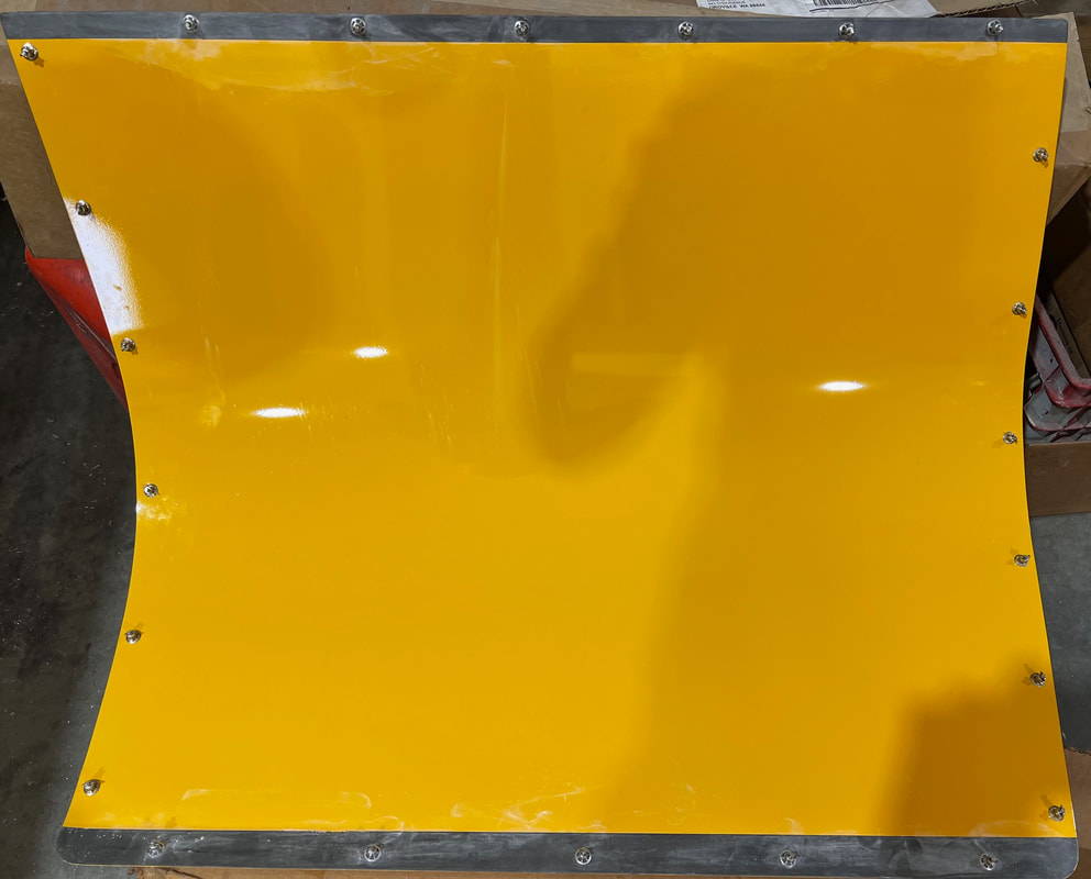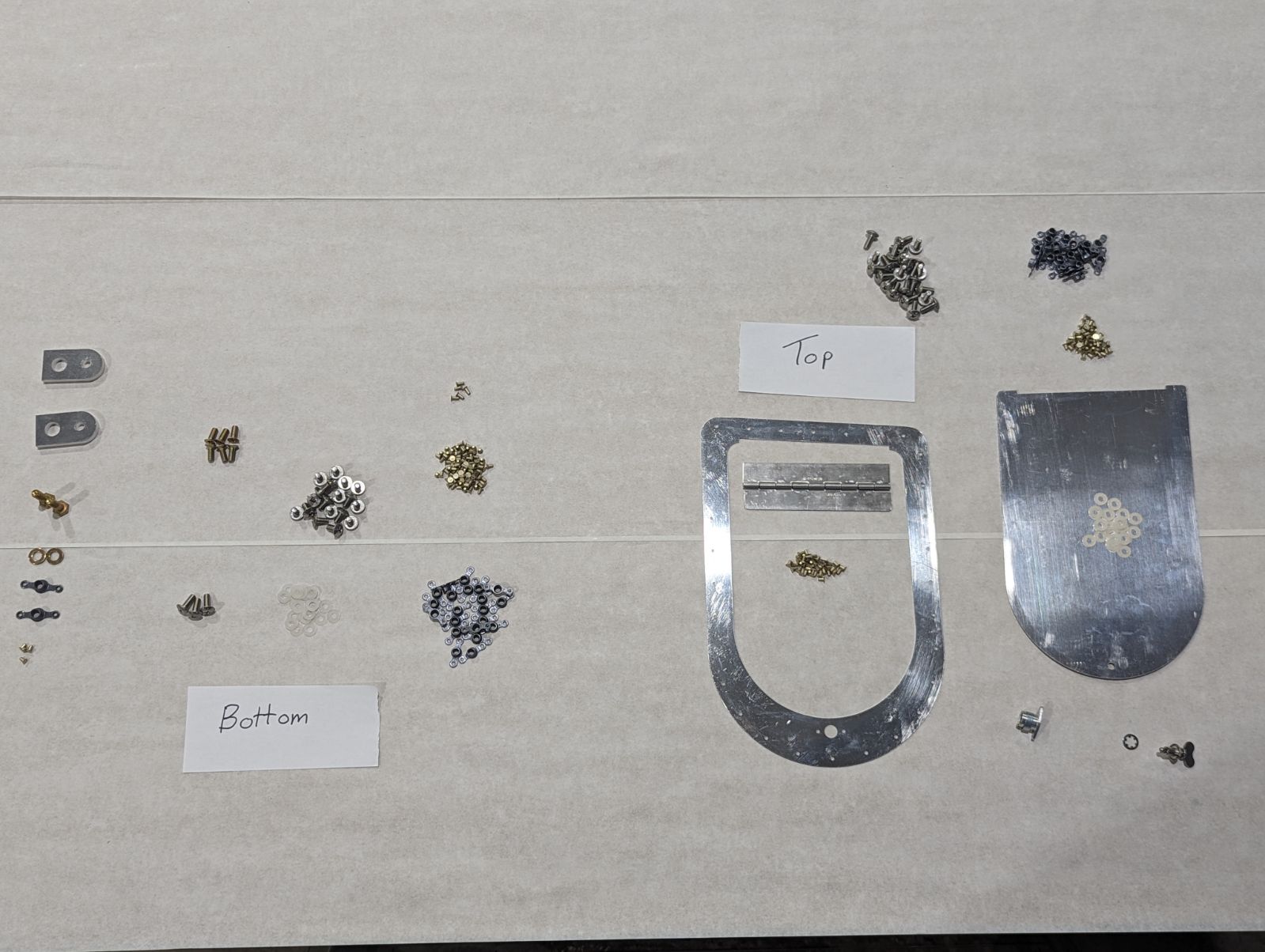
ACE Package - Cowling Top Sides, Bottom and Hardware Kit (Part 4 of 4) **915is**
SKU:
$970.00
$970.00 - $1,384.00
per item
This kit includes aluminum cowl bottom, fiberglass lip, aluminum top sides and also includes the screws and anchor nuts for mounting the top and bottom cowling in place. 1/4 Turn Skybolt fasteners are an option for the top cowling only and highly recommended to save you time. They are different hole spacing so are not easy to install after the screws in this kit have been installed.
INSTALLATION INSTRUCTIONS
STEP 1:
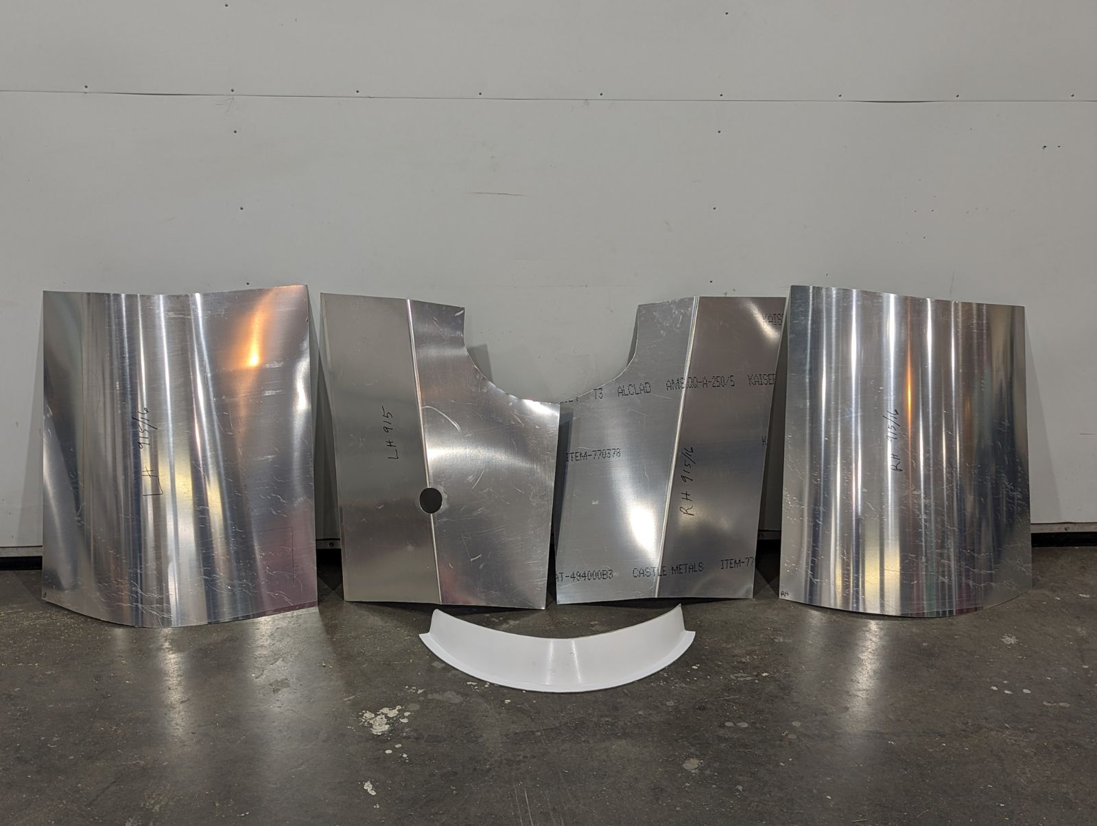
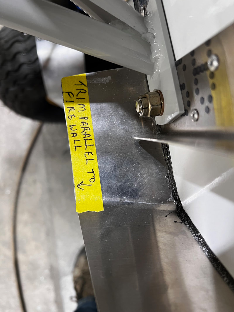
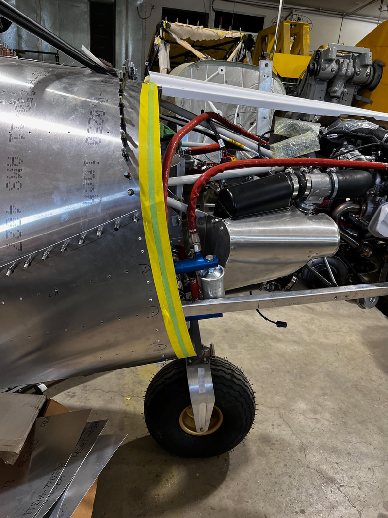
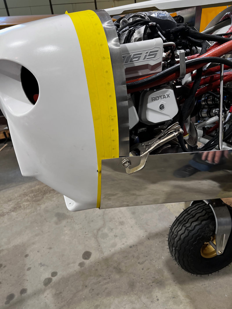
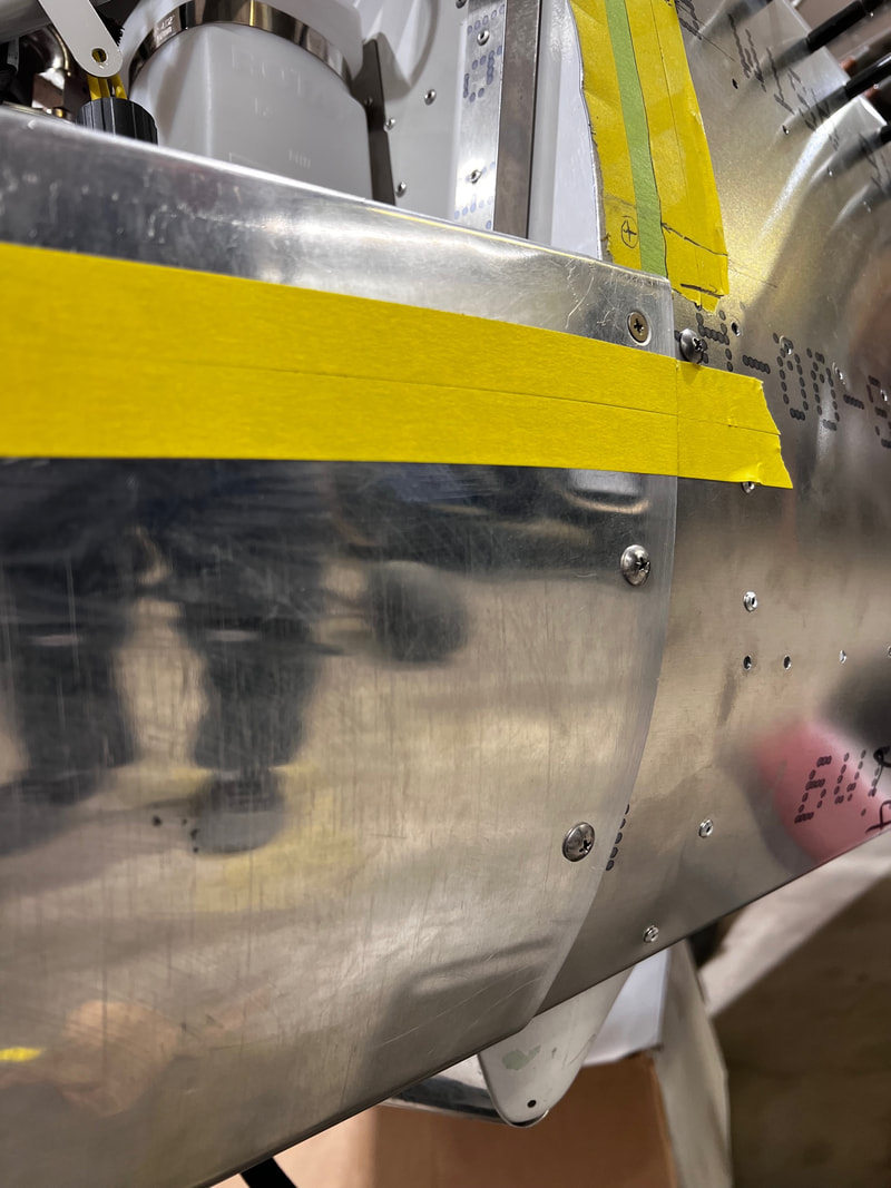
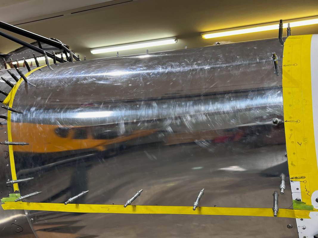
Trim lower forward cheek skins (Lh & Rh) parallel to firewall. Lh shown. Verify nose bowl looks level as fit before.
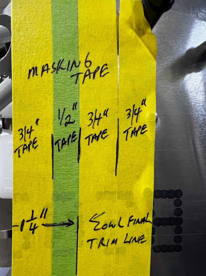
Lay four rows of tape as shown above on both forward sides of cheek skins (lower half only) and nose bowl fiberglass part only three rows of 3/4" only over whole thing. This 1.25" line that you have marked on the cheek skins will eventually be your trim line for the bottom cowl on the back side. On the front side you will eventually trim your lower cowling skin to the edge of the the fiberglass (aft edge of first tape laid).
STEP 2: Fitting of the lower cowling skins
Slide your Lh bottom skin up the exhaust pipe and verify that the corners match the corners of the nose bowl (front) and chin skin (aft). Enlarge the opening for the exhaust pipe if required. Clamp and tape in place. Verify that the cowling fits to the 1.25" mark or farther on the aft side and extends forward of the edge of the fiberglass nose bowl. Adjust forwards or aft to accomplish this.
On 916 skip the exhaust pipe part as that will come at the end and your cowl does not have an exhaust hole in it. Mark a position line on the cowl and nose bowl so that the forward edge of the cowling can be replaced in the same position. Do the same for the aft edge between the cowling and the cheek skin.
On 916 skip the exhaust pipe part as that will come at the end and your cowl does not have an exhaust hole in it. Mark a position line on the cowl and nose bowl so that the forward edge of the cowling can be replaced in the same position. Do the same for the aft edge between the cowling and the cheek skin.
|
|
STEP 3:
Trimming front vertical edge of bottom cowling to exactly match the back edge of the nose bowl fiberglass.
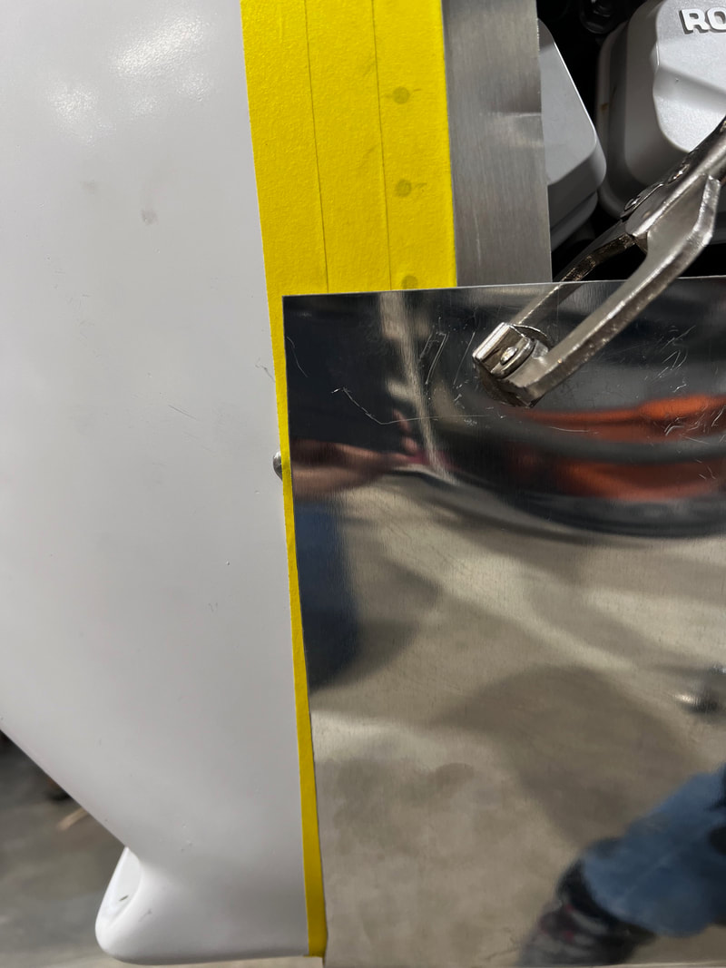
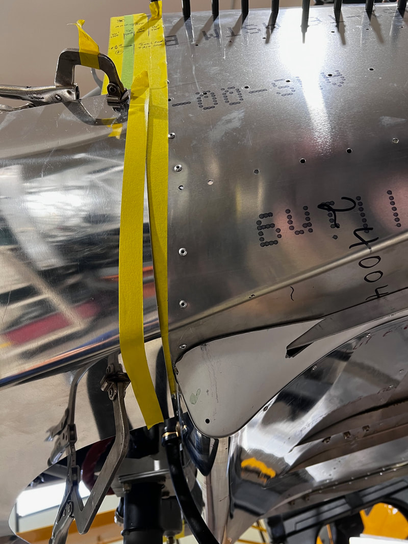
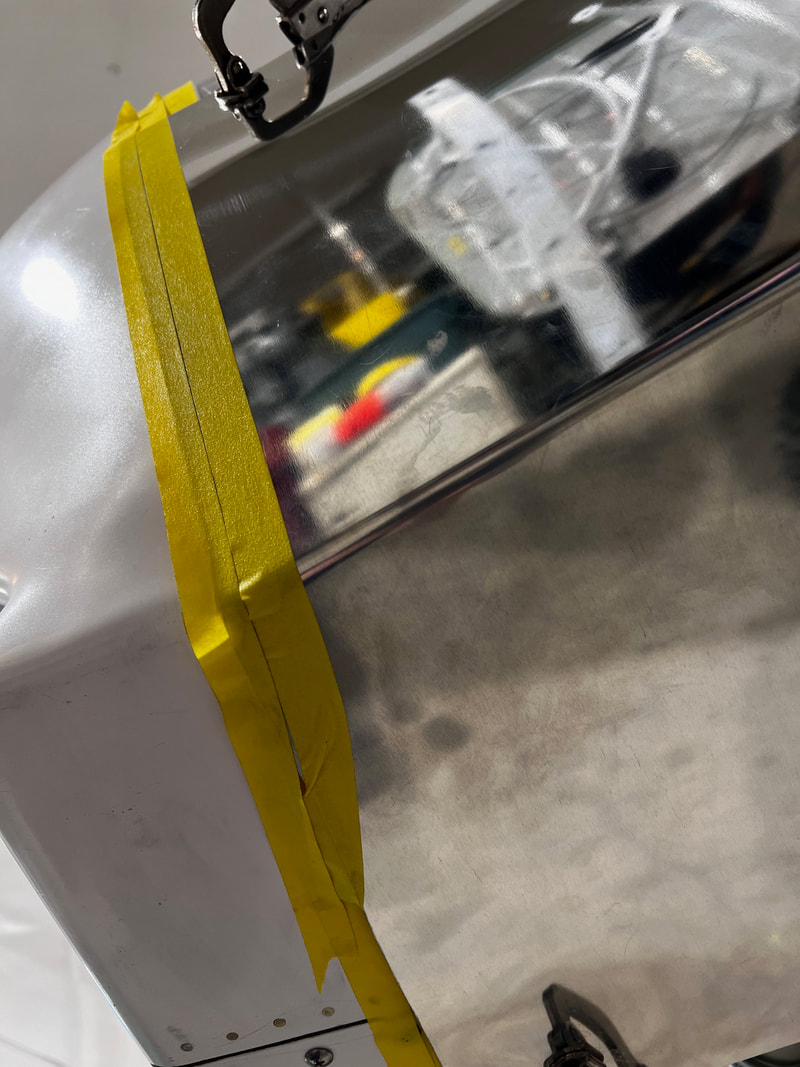
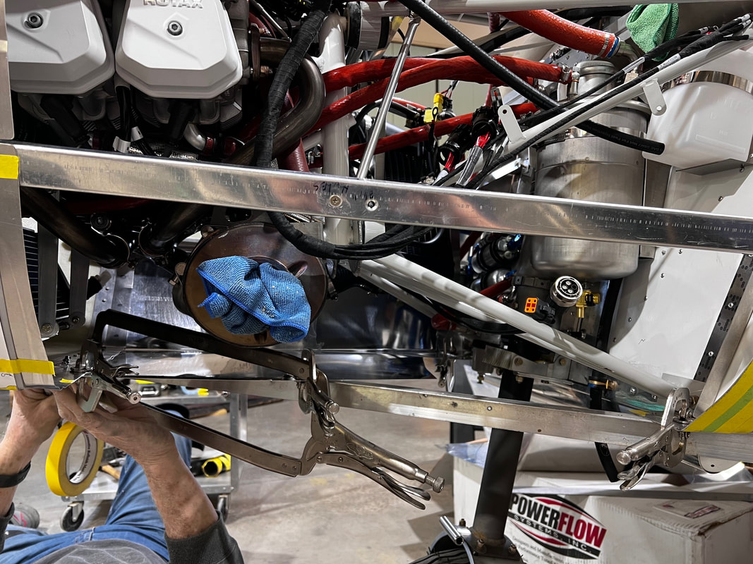
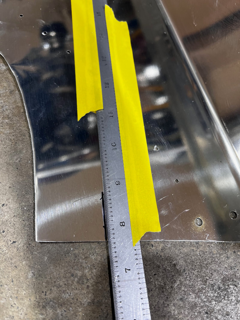
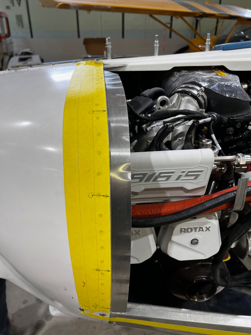
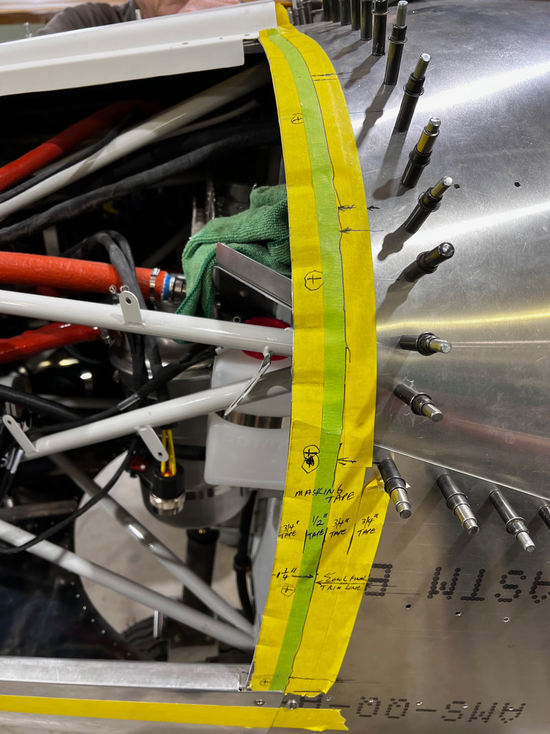
Use your tape as a guide by running a tape line directly over your third tape and on to the cowling if it extends that far forward. If Your cowling does not reach the third tape line run one down the second line. If it did reach run a second tape up against the first tape you just installed. Run a second or third tape line (make it 1/2") so the aft edge of the tape line will be 1/4" from your finished cut line. Remember to only worry about the vertical part and no more than 1" on the bottom. (6th picture down shows how I mark and cut the bottom part at this time) Do not trim bottom forward edge farther than 1". Remove cowling bottom side. Trim to the edge of your tape line. Reinstall and verify that you have a 1/4" overlap. Run a 3/4" tape down the forward edge of the last (aft) 3/4" tape. This should give you the finish cut line. This is shown in green on the pictures for the aft side of the cowling. Run a second tape exactly against this tape as when you pull the cowling to make the final cut the first tape will come off the cowling. The same is done for the aft side but you want a 1.25" overlap. Remove material till you get to within a 1/4" of your final cut trim. Then run a 3/4" tape down the 3rd tape from the left shown in the picture step 1. Once again run a second tape line on the cowling exactly against the first tape edge. Remove cowling and trim both forward and aft sides to the trim line. Hint - It may be best to file the last bit so you do not get waves in the metal from tin snips. Repeat procedure for Rh side only no exhaust pipe to worry about. The intake hole center should be about 10.5" aft of the fiberglass on the nose bowl.
-Run tape lines on the forward and aft edges where the cowling will eventually fit. Final size of cowling will be aft edge of green tape on aft side and aft edge of aft yellow tape on forward side.
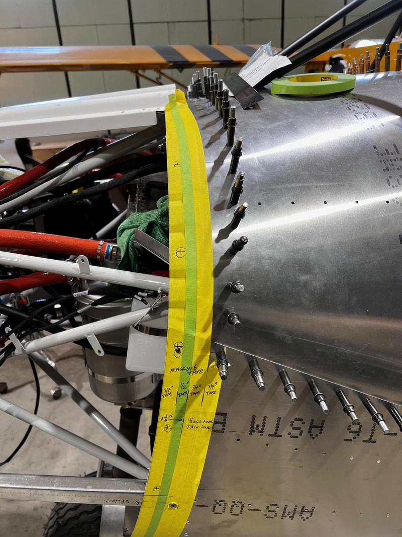
-Use your tape as a guide by running a tape line directly over your third tape and on to the cowling if it extends that far forward. If Your cowling does not reach the third tape line run one down the second line. If it did reach run a second tape up against the first tape you just installed. Remember to only worry about the vertical part and no more than 1" on the bottom. (2nd picture down shows how I mark and cut the bottom part at this time) Do not trim bottom forward edge farther than 1". Remove cowling bottom side. Trim to the edge of your tape line. Reinstall and verify that you have a 3/4" overlap.
-Repeat procedure for Rh side only no exhaust pipe to worry about. The intake hole center should be about 10.5" aft of the fiberglass on the nose bowl.
-Repeat procedure for Rh side only no exhaust pipe to worry about. The intake hole center should be about 10.5" aft of the fiberglass on the nose bowl.
-Cut your tape lines shown above off. This will give you a 3/4" overlap on front end. By adding one more 1/2 in tape to upper picture row you will be at the 1/4" long mark on the front side if trimmed to the back edge of the 1/2" tape. Slowly trim front (most important as it shows) till it matches the contour on the vertical part of the nose bowl. Once front is done trim aft vertical as well. Picture below will make the cowling 3/4" extra long. If the yellow tape was replaced with a 1/2" tape, and cut on the forward side of the tape, you would have a 1/4" overlap on the backside as well. I recommend filing the last 1/8 inch to keep from getting snip marks in the skin. Finish trimming cowling to finished length. (Aft edge of fiberglass nose bowl and aft edge of green tape on cheek skin or 1.25" aft of fwd face of cheek skin.)
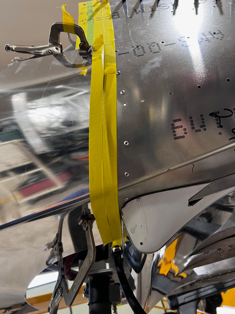
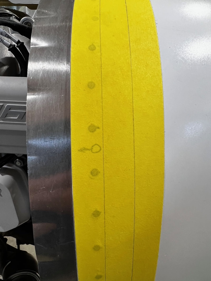
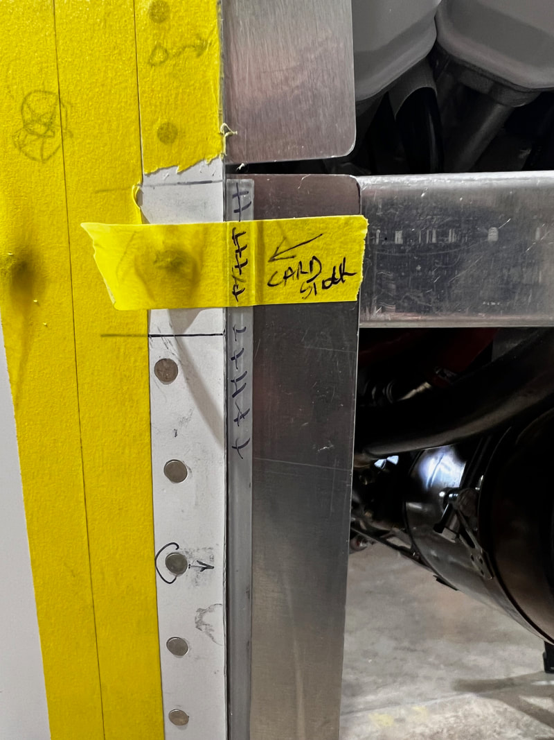
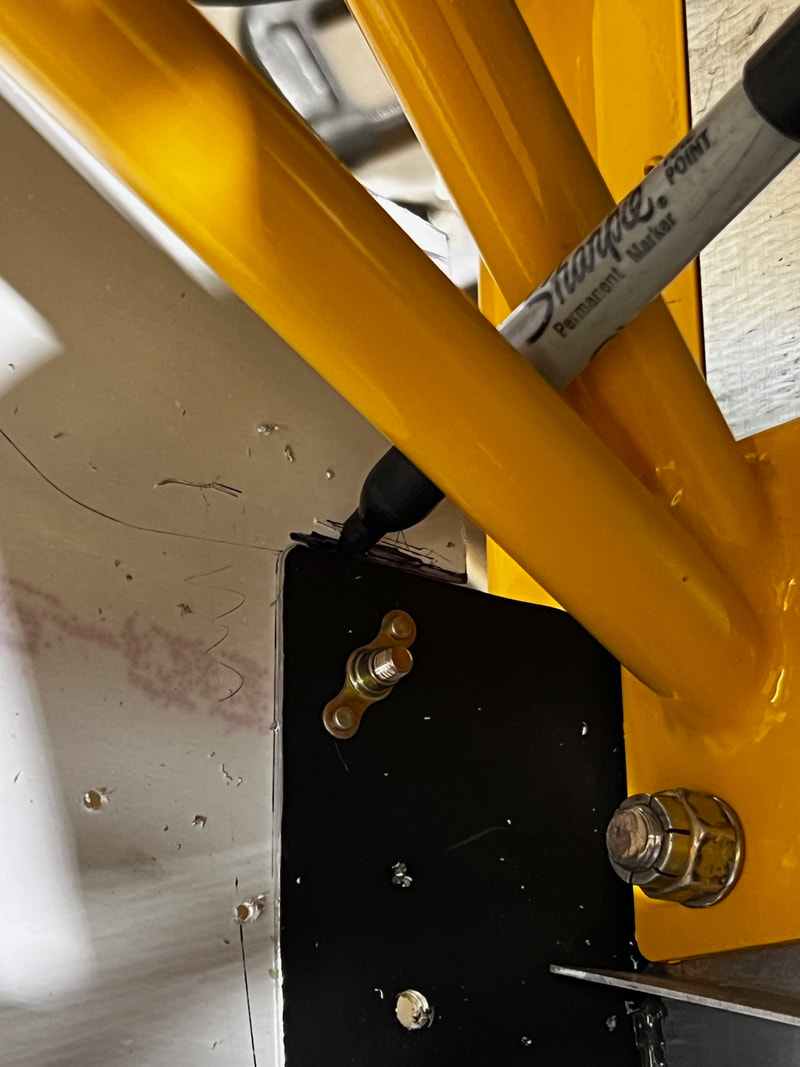
-Cut and tape 1/4" wide strips of cardstock paper to aluminum joiner strip immediately aft of fiberglass on nose bowl. Build this up until your cowl fits flush with the nose bowl fiberglass. This can be done over entire nose bowl. Mark where locations you are able to install fasteners on tape on the fiberglass part of the nose bowl. (shown by a circle with an arrow in picture below)
-Reposition Lh lower skin in position again. Tape or clamp to C channel. Mark a line 9/16" from front of skin at nose bowl and 5/8" from aft end of skin at cheek skin on bottom cowling skin.
-Run a piece of 1/2 " masking tape to mark this line using the front or rear edge of the tape as the line. Using the locations marked for fasteners on the nose bowl mark four holes (close to evenly spaced) on forward vertical edge of bottom cowl.
-Mark three fastener locations on the aft edge of the lower cowling as well.
-The top two holes are to go into the C channel previously fit when installing nose bowl. Be sure they are not too high as to make it difficult to install anchor nuts in C channels. Drill these with a #40 and cleco as you go staring from the bottom corner.
-Complete above for Rh side as well.
-Complete above for Rh side as well.
Now fit the bottom front edge of the cowling skins.
-This is done the same way as you did the sides but clamp a straight edge (angle) across the back of the skins so they do not sag down. By sagging down it changes the cut line at the front edge of the nose bowl. (See picture above.)
Run your 3/4" and 1/2" tape till you are 1/4" from the final cut size. Mark aft side for cutting as well. Trim skins. Reinstall skins and mark final trim size. Trim these skins and reinstall.
-Mark the 9/16" line at the front and 5/8" line at the back on your cowling skin. There should be total of five equally spaced screws at the forward bottom end with the center screw lined up with the center row of screws in your nose bowl split line. Lay out for two screws on the aft edge. One right close to edge of the cheek skin and one right close to the outside corner. Drill these with #40 and cleco as you go working inboard to center from corners.
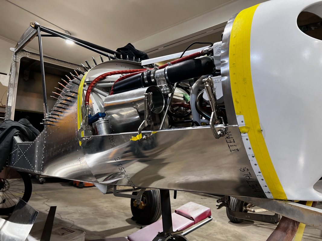
STEP 4: Cowl skirt installation
-Mark inboard edge of cheek skin on top side of cowling skin. This will become your final trim line for bottom opening.
-Place cowl skirt in place clamping in position. This will take the place of the angle previously clamped there. The back ends should come to about 5/16" from the bottom chin skin previously installed with your firewall and centered on the belly of the aircraft.
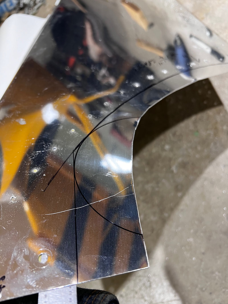
-Mark a line on the bottom cowling halves using this as a guide. This will become part your cut line. Remove cowling halves. Transpose the cheek skin line to the outside of the cowling skin on each side. Extend the cowling cheek skin forward till it meets the line drawn from the cowl skirt. This angle is too sharp to cut, so draw a 3" radius to join the two lines. This can now be cut on each cowl half to give the cowling opening. Reinstall cowling bottom skins with clecos.
-Place cowl skirt in place clamping in position. This will take the place of the angle previously clamped there. The back ends should come to about 5/16" from the bottom chin skin previously installed with your firewall and centered on the belly of the aircraft.
-Mark a line on the bottom cowling halves using this as a guide. This will become part your cut line. Remove cowling halves. Transpose the cheek skin line to the outside of the cowling skin on each side. Extend the cowling cheek skin forward till it meets the line drawn from the cowl skirt. This angle is too sharp to cut, so draw a 3" radius to join the two lines. This can now be cut on each cowl half to give the cowling opening. Reinstall cowling bottom skins with clecos.
-Clamp cowling skirt in position to hold bottom flat. Draw a line from the cut line in your nose bowl to 1/2"off center of your nose gear leg on the Rh lower cowl skin. This is your cut line. To the right of this lay out a double row for rivets 1" apart at approximately 1 inch spacing. They should start at about 3/8" form the cut line you just drew. Make sure your first rivet holes miss the aluminum strips riveted to the nose bowl.
-Run these rivets up to and on the center of cowling skirt flange. I trim the skirt flange to about 3/4" width to look nice. A slight adjustment of the rivet spacing may need to be made to accommodate this. Lay out for rivets at approximately 1" spacing on the cowling skirt starting with the rivets spacing just laid out. The last aft hole on each side will become a screw. Once again hole spacing may need to be adjusted. Be sure last rivet does not come in contact with the fuselage cheek skin. File cheek skin out as required.
-Drill #40 and cleco as you go all holes just marked.
Remove cowling skins from aircraft. Trim Rh skin to line marked above. The Lh skin can be trimmed to 3/8" from the last row of holes drilled in it.
-Place the cowling doubler angle on the inside of Lh cowling skin so that the angle is even with the cut just made. Clamp and back drill the double row of holes just drilled in the two skins. Trim aft end to match opening in cowling. Cut the vertical part of the angle at a 45 degree angle. Trim the Lh side of the doubler angle to give a 3/8" edge distance.
-Deburr all holes. Dimple double row of holes in doubler angle, and each lower cowling side skin except last two holes as they go through the cowling skirt. Countersink (100 degree) the cowl skirt to accept the heads of the 3/32 rivets supplied. They should just sit flat. Do not over countersink. At this point if you are doing a 916-- Go to 916 instructions for fitting your exhaust pipe to the Lh side of the lower cowling.
At this point if you are doing a 916-- Go to 916 instructions for fitting your exhaust pipe to the Lh side of the lower cowling.
STEP 5: Assembly
-Rivet the four pieces that make up the lower cowling together.
-Cleco the bottom cowl in position.
-Starting in the middle upsize the #40 screw holes to #10 and cleco as you work you way evenly outboard and up. Start on the aft row as well so you finish at the top on each side front and back at the same time. Drill the hole in the cowling skirt as well if not already done.
-Mark the lower cowl sides even with the top of the C channel. This can be cut here or if you have the equipment cut it 5/16" away from the line and put a 90 degree bend in it so it folds over the C channel. This just adds rigidity and you are less likely to snag on it.
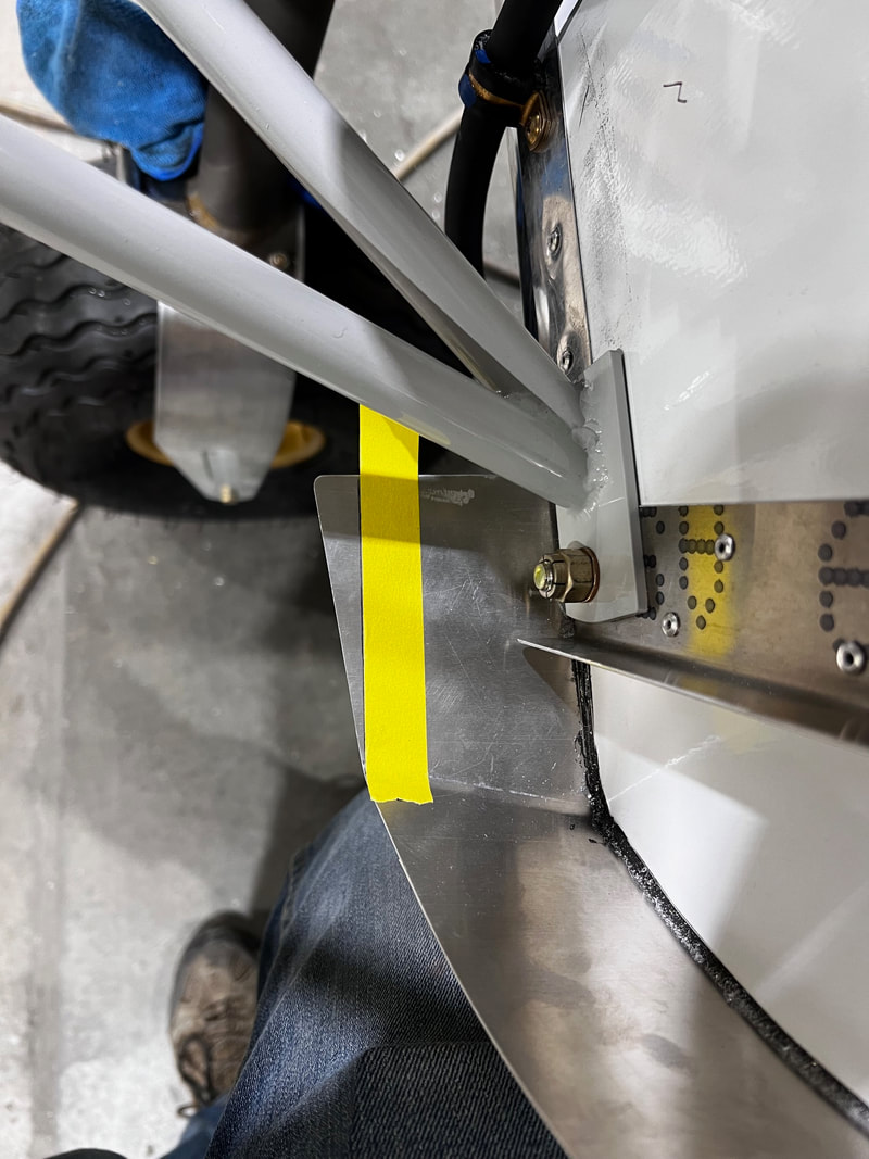
-Pick up the center hole in the sides of the bottom cowl. This hole is in the steel bracket attached to the stainless rods. Forward one has a screw already the other hole needs to be picked up in the cowl skin on each side.
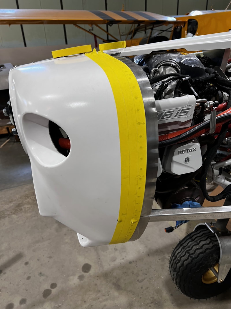
-Remove bottom cowl assembly and drill for and install anchor nuts in the nose bowl and cheek skins. Leave card stock shims in place till side cowlings are completely fit. Countersink rivet holes so rivets are proud. (sticking up slightly).
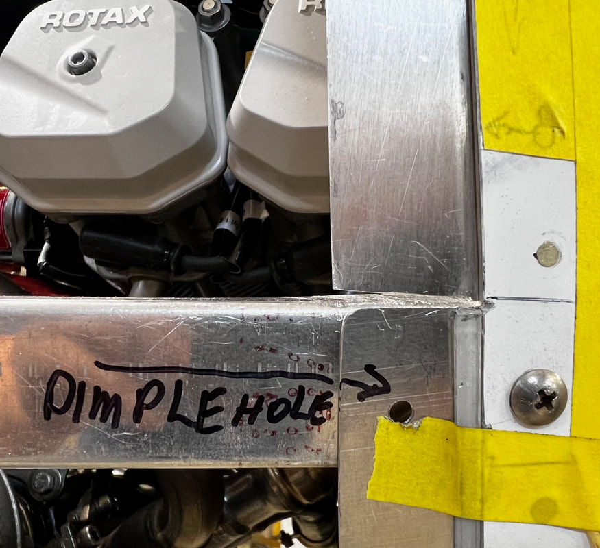
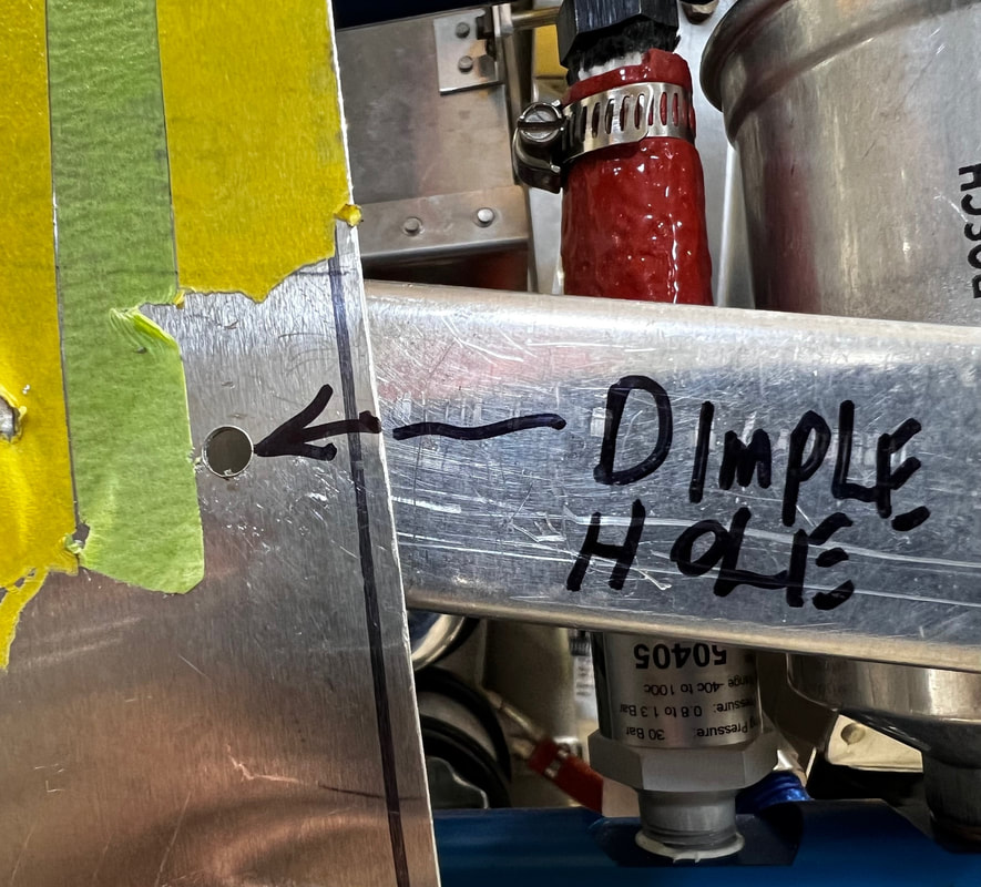
-The top three holes in the cowl on each side need to be dimpled for a #10 screw. Remove the cowl C channels. Dimple the forward and aft holes in cowling and C channel as well as the middle hole if it is not already dimpled for a #10 screw.
-Install anchor nuts on the forward and aft holes just dimpled in C channels. Be sure to use the correct anchor nuts for dimpled screws. You can now file an extra 1/16" off the front of the bottom cowling all the way around till you have a nice even gap between the cowling and the nose bowl that will give enough room that the paint will not be chipped off every time you try and remove or install the cowling. Be sure you have a minimum of 5/16" clearance between the exhaust pipe and the cowling. (915) Check after running engine (first run and again after first flight) for wear marks and trim more as required. Repeat as required.
-Bottom cowl can now be screwed into position ready for the top side cowling installation (Do not overtighten forward screws as it could deform aluminum as it is not supported all around fastener just a 1/4" at the front.) or go to Induction Connection kit for installing the air filter, scoop and temperature sensors on the Rh side of the bottom cowling.
-Cleco the bottom cowl in position.
-Starting in the middle upsize the #40 screw holes to #10 and cleco as you work you way evenly outboard and up. Start on the aft row as well so you finish at the top on each side front and back at the same time. Drill the hole in the cowling skirt as well if not already done.
-Mark the lower cowl sides even with the top of the C channel. This can be cut here or if you have the equipment cut it 5/16" away from the line and put a 90 degree bend in it so it folds over the C channel. This just adds rigidity and you are less likely to snag on it.
-Pick up the center hole in the sides of the bottom cowl. This hole is in the steel bracket attached to the stainless rods. Forward one has a screw already the other hole needs to be picked up in the cowl skin on each side.
-Remove bottom cowl assembly and drill for and install anchor nuts in the nose bowl and cheek skins. Leave card stock shims in place till side cowlings are completely fit. Countersink rivet holes so rivets are proud. (sticking up slightly).
-The top three holes in the cowl on each side need to be dimpled for a #10 screw. Remove the cowl C channels. Dimple the forward and aft holes in cowling and C channel as well as the middle hole if it is not already dimpled for a #10 screw.
-Install anchor nuts on the forward and aft holes just dimpled in C channels. Be sure to use the correct anchor nuts for dimpled screws. You can now file an extra 1/16" off the front of the bottom cowling all the way around till you have a nice even gap between the cowling and the nose bowl that will give enough room that the paint will not be chipped off every time you try and remove or install the cowling. Be sure you have a minimum of 5/16" clearance between the exhaust pipe and the cowling. (915) Check after running engine (first run and again after first flight) for wear marks and trim more as required. Repeat as required.
-Bottom cowl can now be screwed into position ready for the top side cowling installation (Do not overtighten forward screws as it could deform aluminum as it is not supported all around fastener just a 1/4" at the front.) or go to Induction Connection kit for installing the air filter, scoop and temperature sensors on the Rh side of the bottom cowling.
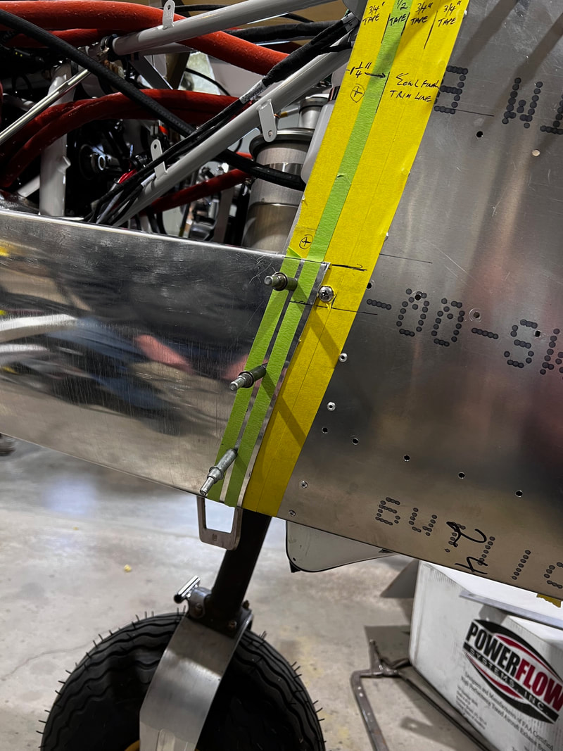
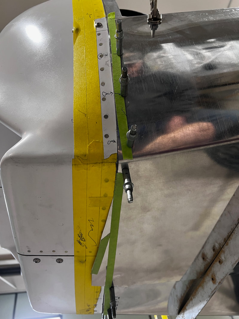
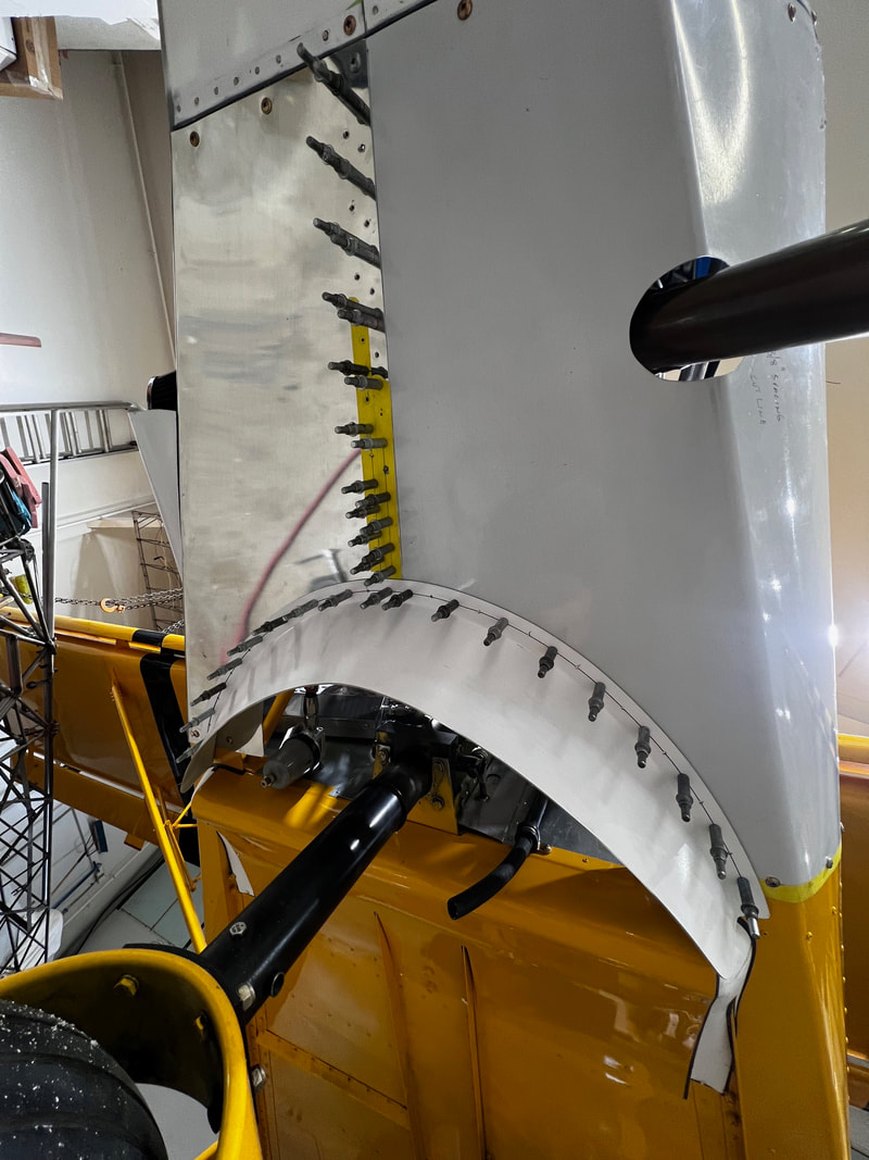
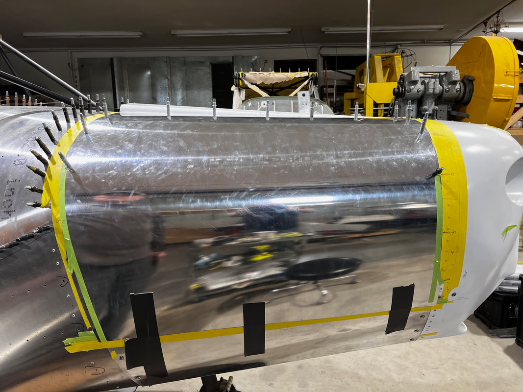
STEP 6: Fitting the side cowling skins:
-Run a tape line from the back edge of the fiberglass center cowling down to the back edge of the lower cowling. Make it a nice smooth looking arc. This will become your final trim line for the aft edge of the cowling. Repeat other side. Add an additional couple of tape lines aft of that so you have a guide for trimming and fitting.
-Your fastener row will start out at 1/2" at the top and grow to 5/8" at the bottom to line up nicely with the bottom cowling on the aft side.
-Place a tape line going down the center of the screws in the C channel on each side where you top cowling fasteners are going to eventually be located. Place a second and 3rd piece of 3/4" tape below that to help you with the trimming later.
-Find the center of the flange for the side cowling to fit onto on the center top fiberglass cowling. Mark where you are going to place your fasteners. Be sure there is no interference with the center support bracket. The last fastener will be in the space previously left in the U channel at the back of the center cowl a few inches from the very aft end. Position an additional 5 fasteners at equal spacing in front of it. The very forward or seventh fastener will be installed in the stainless nose bowl doubler slightly outboard of the row in the center cowling. Make some marks, tape line etc. so you can drill in the center of the flange when the cowl skin is in position.
-Check with a straight edge that from the nose bowl to 1.25" aft on the top skin is parallel. You will have to flute the back skin if not already done so when the nose bowl to side cowl strips were installed. Be sure not to flute where a cowling fastener is to be located or flute past where the cowl skin will cover.
-Position and tape side skin in position such that it overlaps at least one of the tape lines on the nose bowl and gives at least 1" overlap at the top with 1.25" at the bottom. If this can not be done you may have to take an 1/8" off either the forward or aft inboard end tapering to zero at the other end. If the cowl fits better moved inboard take up to 3/4" off the inboard end. Verify there is edge distance on the bottom by the C channel before cutting. This can be repeated as long as you have edge distance.
-Drill the 6 holes through cowling and center fiberglass with #40 and cleco as you go. This ensures the same positioning of the skin.
-Trim the forward edge and aft edge of the side skin to within 1/4 " of the final trim line as before on the lower cowling.
-Trim to final size starting from the top (inboard) and working down (outboard).
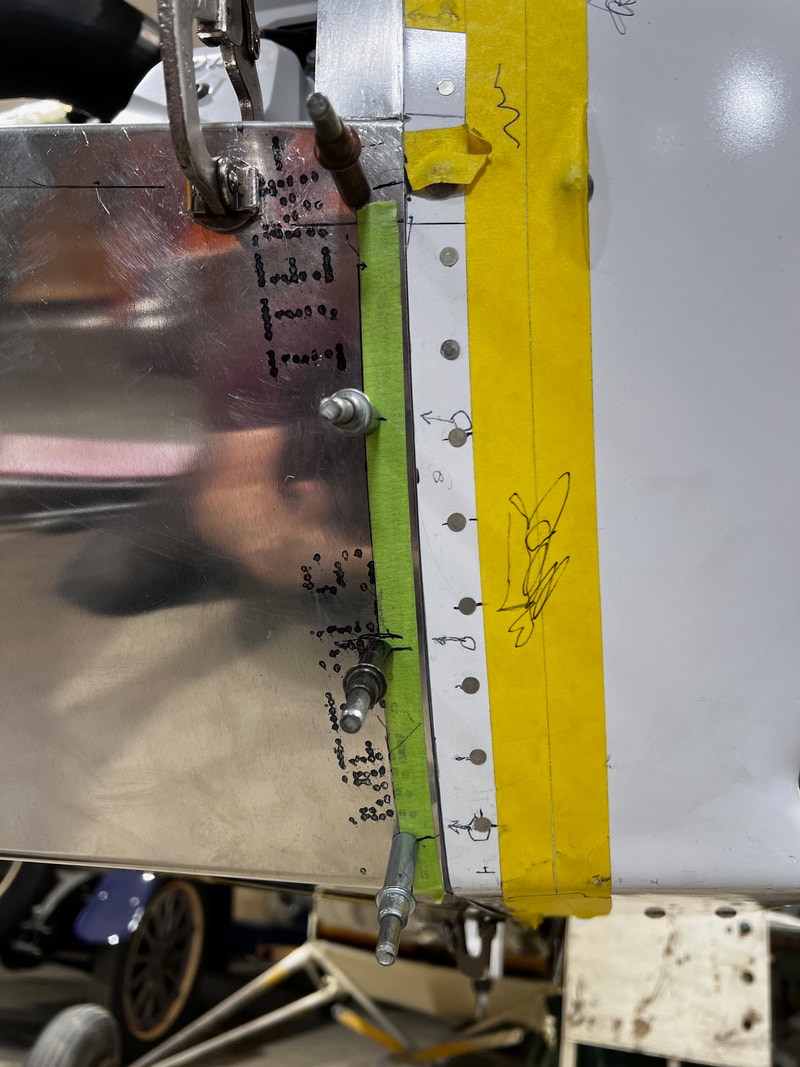
-Place a tape line 9/16' from the fiberglass nose bowl for your fastener row on the forward side fasteners. Your aft row will follow the 1/2" to 5/8" line marked earlier. Mark your forward fastener holes spacing out. Inboard fastener goes in the stainless nose bowl bracket. The outboard most hole is about 1" above the top of the C channel. There should be 5 equal spaces and 4 fasteners located between the two.
-The aft row will have 6 fasteners total. The bottom outboard hole will be about 1" above the C channel and there will be 6 equal spaces between it and the last hole in the fiberglass center cowling.
-Mark your center line for fasteners in the C channel using the tape lines previously laid down. Place one near the front so it does not interfere with the faster nut plate for the bottom skin top screw. Lay out 5 equally spaced fasteners total on the bottom going into the C channel. (Be sure not to make too high where you can not reach them to install later.) Drill and cleco these with a # 40 as well.
-Trim to final size starting from the top (inboard) and working down (outboard).
-Place a tape line 9/16' from the fiberglass nose bowl for your fastener row on the forward side fasteners. Your aft row will follow the 1/2" to 5/8" line marked earlier. Mark your forward fastener holes spacing out. Inboard fastener goes in the stainless nose bowl bracket. The outboard most hole is about 1" above the top of the C channel. There should be 5 equal spaces and 4 fasteners located between the two.
-The aft row will have 6 fasteners total. The bottom outboard hole will be about 1" above the C channel and there will be 6 equal spaces between it and the last hole in the fiberglass center cowling.
-Mark your center line for fasteners in the C channel using the tape lines previously laid down. Place one near the front so it does not interfere with the faster nut plate for the bottom skin top screw. Lay out 5 equally spaced fasteners total on the bottom going into the C channel. (Be sure not to make too high where you can not reach them to install later.) Drill and cleco these with a # 40 as well.
STEP 7:
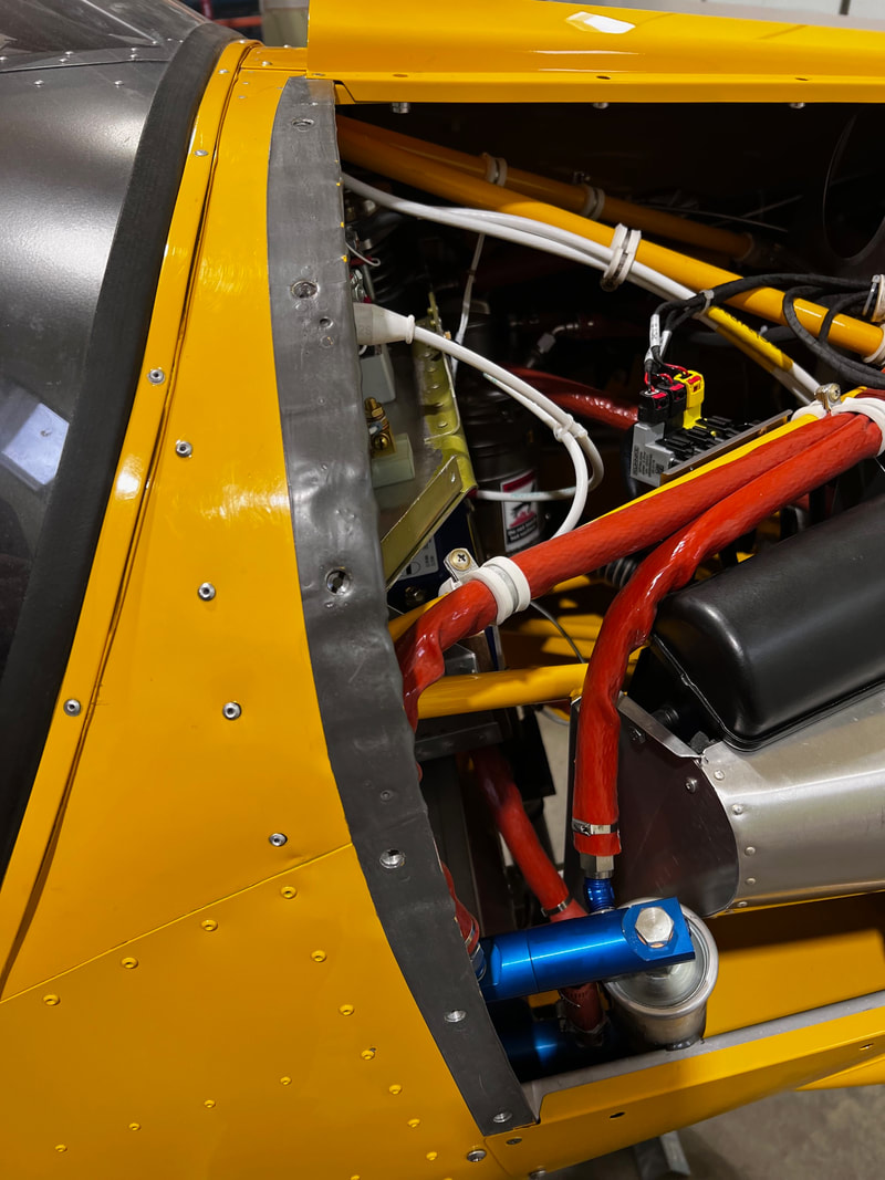
-On the Lh side you can now install the oil access door. See instructions for "Cowling access door Kit (5.25x8 inch opening)" under optimization kits. Install the fuse box cooling scoop in the Lh side cowling. See fuse box mounting and cooling kit for instructions.
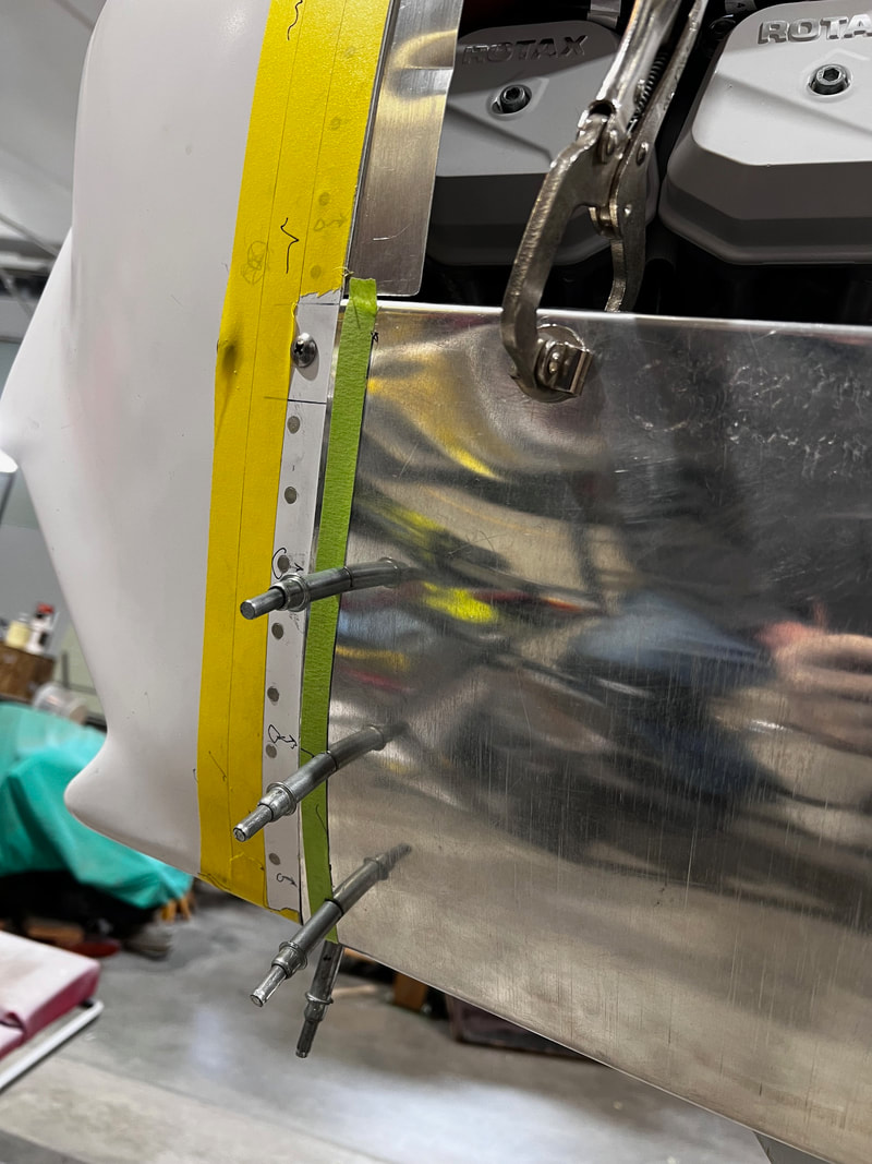
STEP 8: Side cowl fasteners
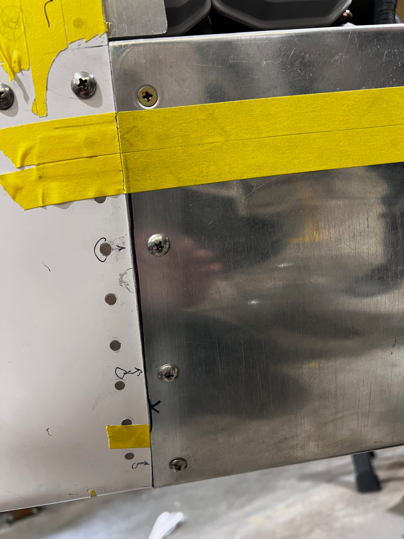
-With side cowlings in position, upsize all the #40 screw holes to #10 for screws and anchor nuts or 1/4" for Skybolt fasteners (see note below). Cleco as you go. Remove cowling and deburr holes. You can now file off 1/16" from the front edge to give paint clearance as done earlier on the bottom cowling. Take your time and make the line nice and strait and even. This will be seen by everyone. Use a screw and anchor nut to drill for anchor nut installation. Do not install anchor nut rivets through bottom cowling when installing in C channels. Countersink holes in top forward and aft sides slightly proud.
NOTE (If you are installing 1/4 turn Skybolt fasteners use one to pick up the two #40 rivet holes. Remove fastener and receptacle. Upsize the main center hole to 5/16". Deburr holes. Countersink proud rivet holes. Install 1/4 turn nut plates. Be sure to upsize the correct holes in the bottom cowling to 5/16" as well but do not rivet the receptacle to the bottom skin just the C channel.). Once your cowling is painted install 1/4 turn fasteners. Adjust length of each receptacle as per Skybolt installation instructions on there website after installing a bead of (Proseal 1422B-2, CS3204B2 or equivalent)
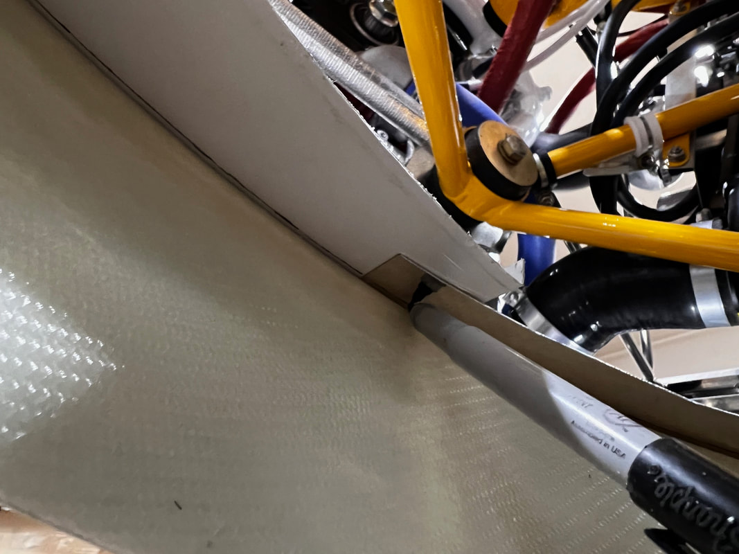
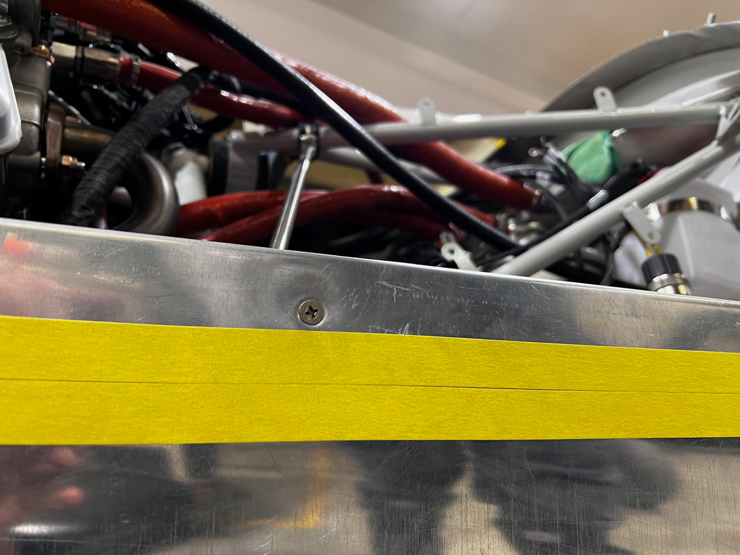
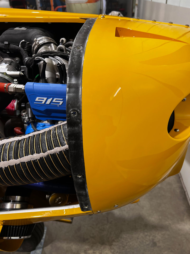
-- FOR ALL INSTALATIONS --- Place a bead of Proseal (1422B-2 , CS3204B2 or equivalent) on the forward and aft edges of the nose bowl and tub cowl skins where the cowling overlaps. I place a thin even layer on the top and bottom of the side cowling as well. (shown in second picture below) Smooth this out to take the place of your cardboard shims used in fitting the cowling.)
It also fills in the divots caused by crimping the metal. Soapy water keeps it from sticking to things when you are smoothing it out. Once this has dried for a day or two (rubber consistency like a tire), rub with baby powder so it will not tend to stick to the cowling. (Be sure to remove the unlock pin when finished adjusting fastener length for the 1/4 turn fasteners).
NOTE (If you are installing 1/4 turn Skybolt fasteners use one to pick up the two #40 rivet holes. Remove fastener and receptacle. Upsize the main center hole to 5/16". Deburr holes. Countersink proud rivet holes. Install 1/4 turn nut plates. Be sure to upsize the correct holes in the bottom cowling to 5/16" as well but do not rivet the receptacle to the bottom skin just the C channel.). Once your cowling is painted install 1/4 turn fasteners. Adjust length of each receptacle as per Skybolt installation instructions on there website after installing a bead of (Proseal 1422B-2, CS3204B2 or equivalent)
-- FOR ALL INSTALATIONS --- Place a bead of Proseal (1422B-2 , CS3204B2 or equivalent) on the forward and aft edges of the nose bowl and tub cowl skins where the cowling overlaps. I place a thin even layer on the top and bottom of the side cowling as well. (shown in second picture below) Smooth this out to take the place of your cardboard shims used in fitting the cowling.)
It also fills in the divots caused by crimping the metal. Soapy water keeps it from sticking to things when you are smoothing it out. Once this has dried for a day or two (rubber consistency like a tire), rub with baby powder so it will not tend to stick to the cowling. (Be sure to remove the unlock pin when finished adjusting fastener length for the 1/4 turn fasteners).
This just shows the proseal rub strip on the top and bottom edge of the Rh cowling.