- Zenith 750 w/ 915 (✔)
- >
- Fuel System Kits - 916is
- >
- Fuselage Fuel Return Line Kit
Fuselage Fuel Return Line Kit
SKU:
SIFS 25K 912/915
$208.12
$208.12
Unavailable
per item
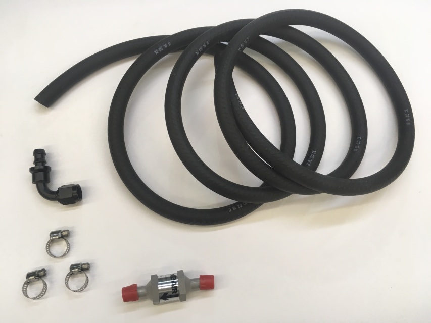
This Fuselage Fuel Return Line Kit includes the Fuel Return Line and all necessary fittings. It also comes complete with a one-way check valve for fuel return!
INSTALLATION INSTRUCTIONS
STEP 1:
The routing of the fuselage fuel return line kit follows the Fuselage Fuel Feed Line Kit, only it sits below the feed line.
Run the fuel line from the fuel valve to the Lh side of the fuselage, running the line just under the angle that the upper engine mount is bolted to. Then, continue aft under this angle to the hole at the front of the pilot's seat, and carry the line aft of the pilot's seat to the front side of the landing gear tunnel. You will need to drill a hole just above the landing gear tunnel so the fuel feed AND return line can reach the header tank and/or sump drain (this is for version 5 fuselages).
NOTE 1: When drilling, be sure you do not drill into the steel landing gear/strut attach fitting on the front side of the landing gear tunnel. For earlier version fuselages, drill your holes above the landing gear tunnel on the aft side. Ensure your holes are drilled inboard of the aft door post (the fuel lines (vent and feed) will be completely covered by the existing structure).
NOTE 2: The fuel lines (vent and feed) will be exposed (Version 5) from the aft side of the seat floor panel to the header tank and sump drain. You can cover the fuel lines over the landing gear tunnel with a fuel line protective cover kit (version 5). There is also a header tank closeout panel kit (version 5) to prevent cargo from getting caught in the fuel lines, as well as a similar kit for earlier versions.
NOTE 3: This route is only our recommendation. You may route these lines in another configuration if you wish.
The following photo shows the positioning of the return line through the firewall. The top 9/16" diameter hole is where the return line is connected on the aft side of the firewall.
The following slideshow can guide you as you route the fuel return line.
STEP 2:
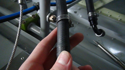
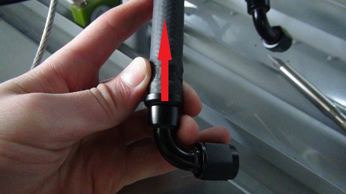
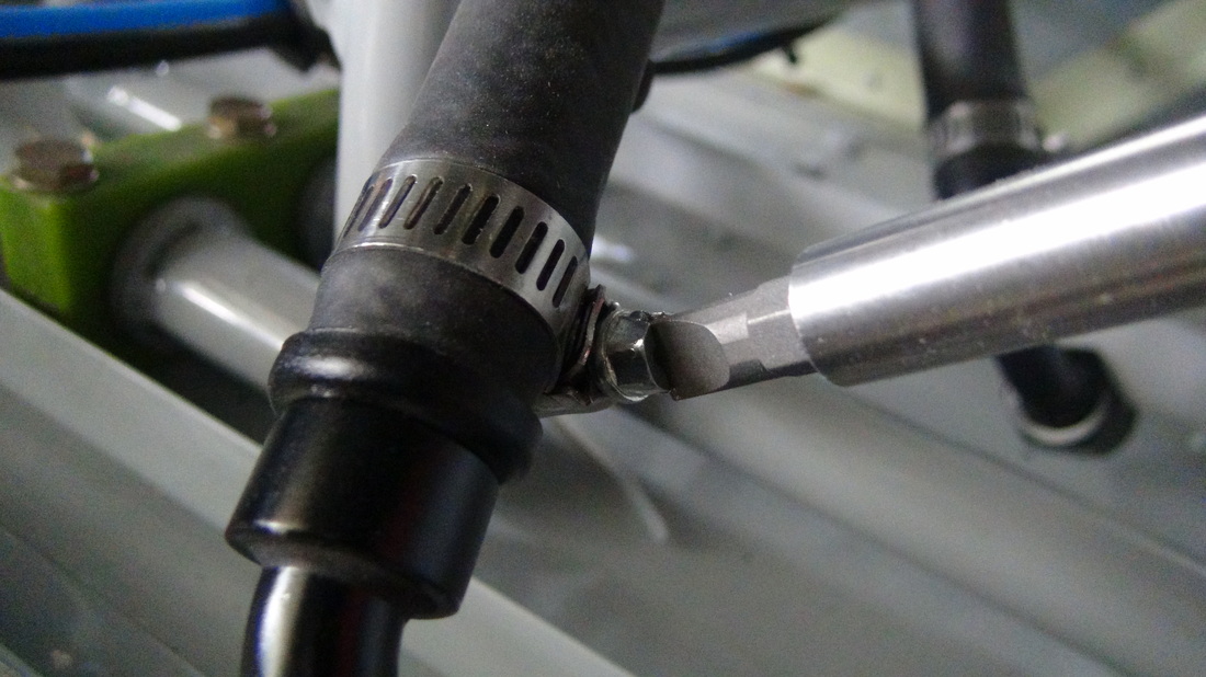
Now lets build your Fuel Return Line. Slide one of your new worm gear clamps onto the end of the Fuel Hose (The fuel hose end that is closest to the Firewall. Not the end that is to be connected to your Header Tank). Then push your new 90-degree fitting onto the same end of that hose.
Now tighten your 90-degree fitting onto the upper blue fuel filter mounting bracket.
STEP 3:
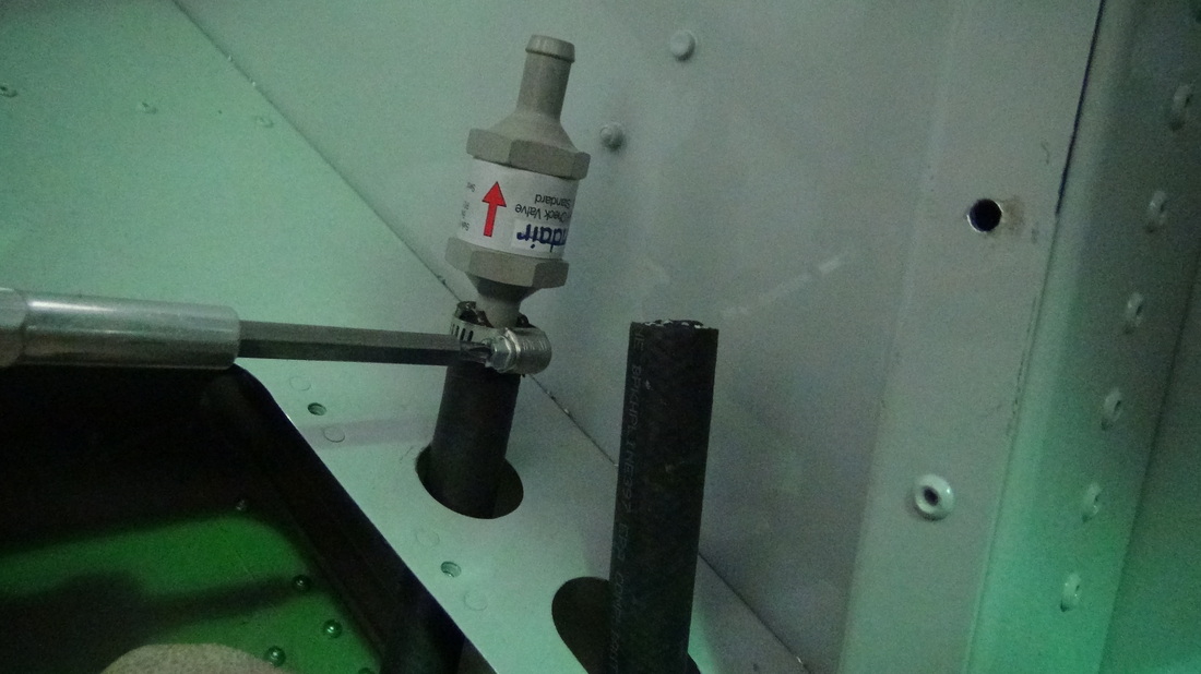
At this point, run your lines through the route as described in Step 1. Attach the included One-Way check valve Return to the end of your Return Line.
NOTE: You will have to cut about 1.5" off the line to go above the One-Way check valve (shown in Completed pictures).
Put together the parts on the forward side of the firewall as shown.
NOTE: The orange lines are your Flexible Fuel line Kit lines.