
Electronics Fuse Box Installation and Cooling Assembly Kit - 915is, 916is
SKU:
SFF 74AK5is
$500.00
$500.00
per item
This Electric Fuse Box Installation Kit includes everything you need to install your Electric Fuse Box. The detailed instructions below show how to install this kit, which is very quick and easy.
INSTALLATION INSTRUCTIONS
STEP 1:
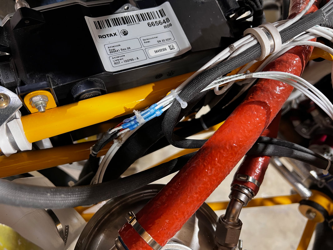
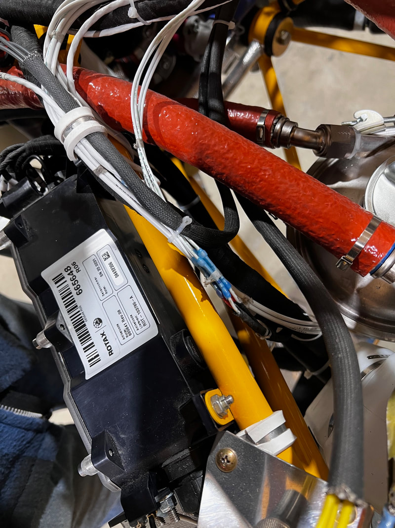
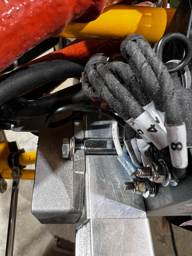
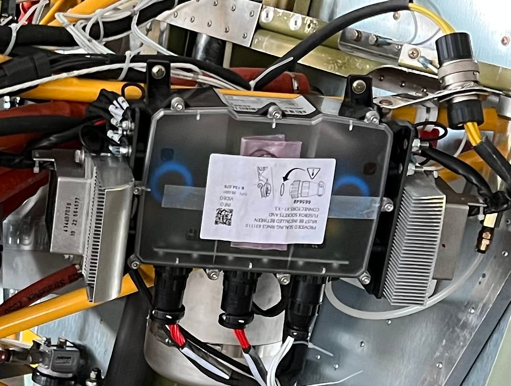
Install the Fuse box on the Lh side of the ACE kit engine mount by screwing it to the tabs installed using the hardware provided. See the pictures below.
The top and bottom fasteners are the same.
The top and bottom fasteners are the same.
STEP 2:
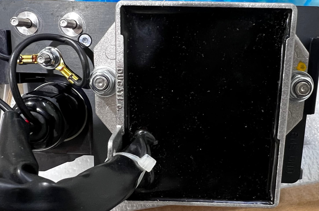
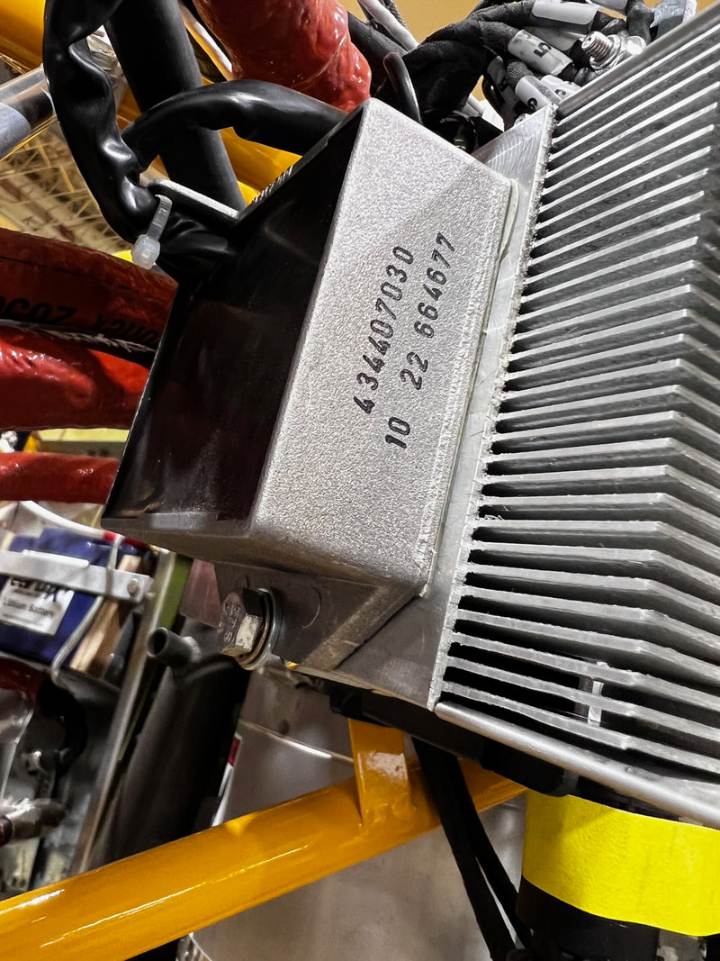
Remove the two nuts and 4 washers holding the regulators in position to the ends of the fuse box. Save the large washers.
Keep the heat sink material on the regulator. Install the two cut washers, as shown, on each end with a coupling nut. Install regular round washers and coupling nut on the other end.
Keep the heat sink material on the regulator. Install the two cut washers, as shown, on each end with a coupling nut. Install regular round washers and coupling nut on the other end.
STEP 3:
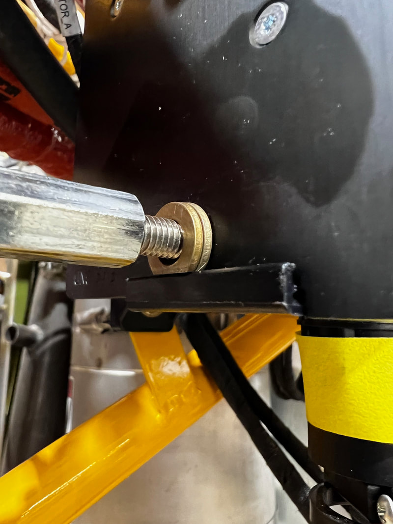
Install the blue heat dissipater cooling fins in position. The one with the radius goes on the back side (the forward one shown is not blue like yours). Install the regulator in its new position with a bolt, lock washer, and the saved washer (from step 1) going into the coupling nuts.
STEP 4:
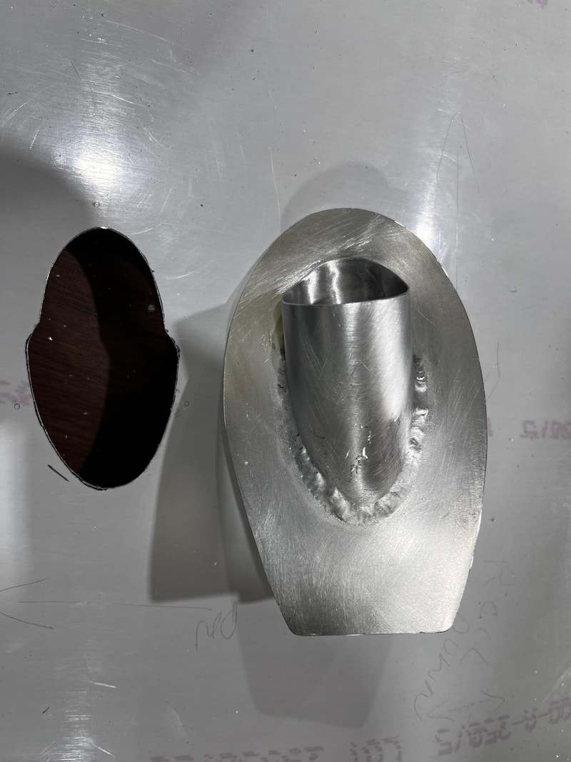
Slide the scoop onto the forward heat dissipater scoop, facing forward. A tiny bit of silicone or proseal applied where they join will hold it from coming loose.
STEP 5:
This is to be accomplished after the Lh side cowling is fit.
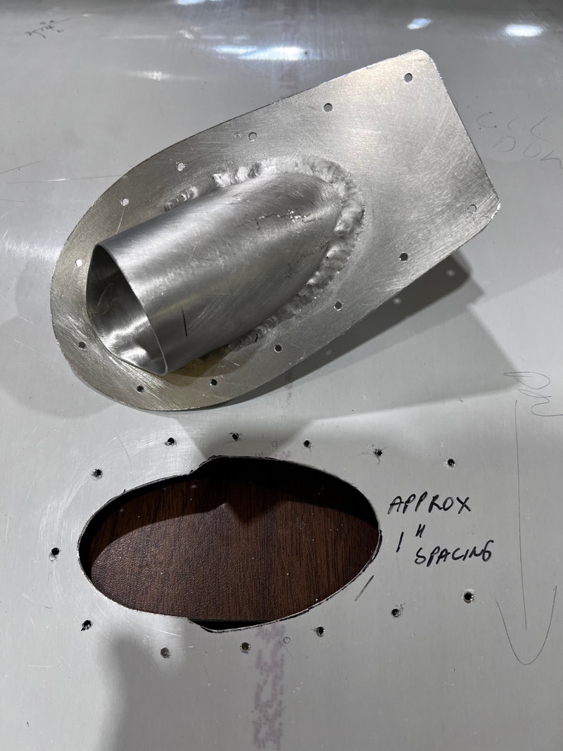
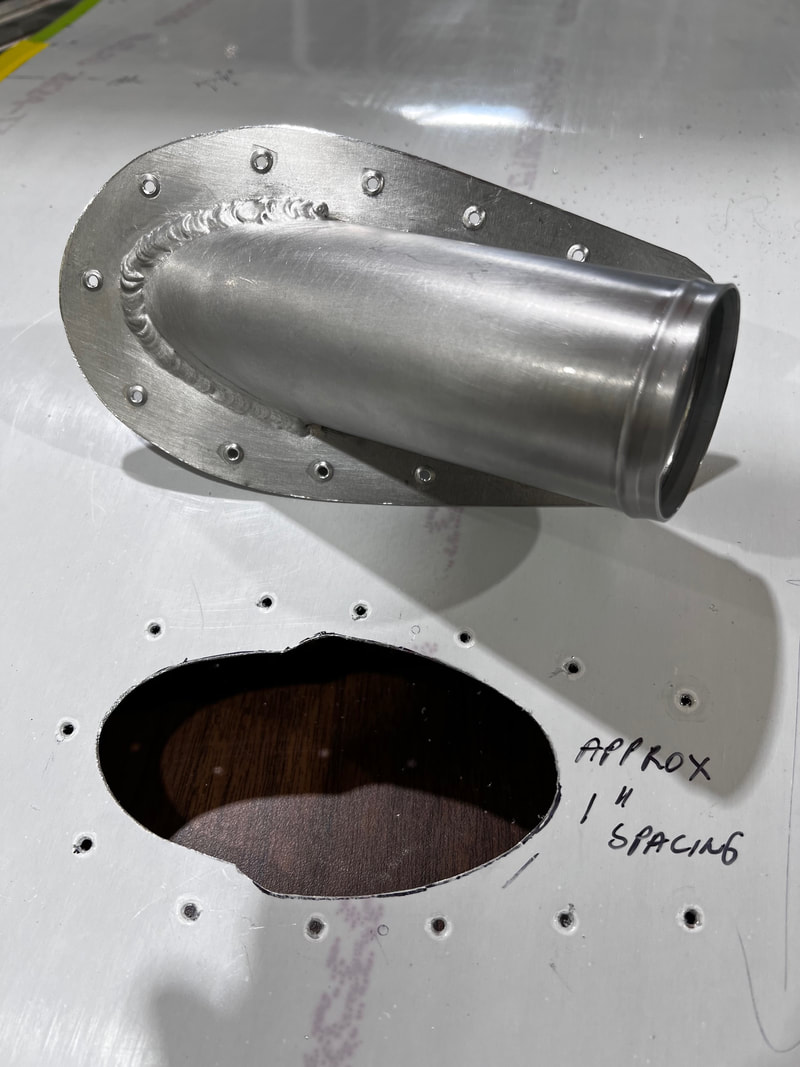
Mark a point about 7" up from the cowling support rail and 9.5" aft of the cowling. Carefully cut a hole to fit the scoop (the scoop is installed from inside). Take your time for a better-looking job. The scoop should be fit parallel to the line of flight. Trim your scoop and drill #40 holes at about 1" spacing.
HINT: do not drill a hole in line with the back, as the outlet is in the way when it comes to riveting it in place.
Deburr all holes and dimple inboard.
Rivet scoop in place.
STEP 6:
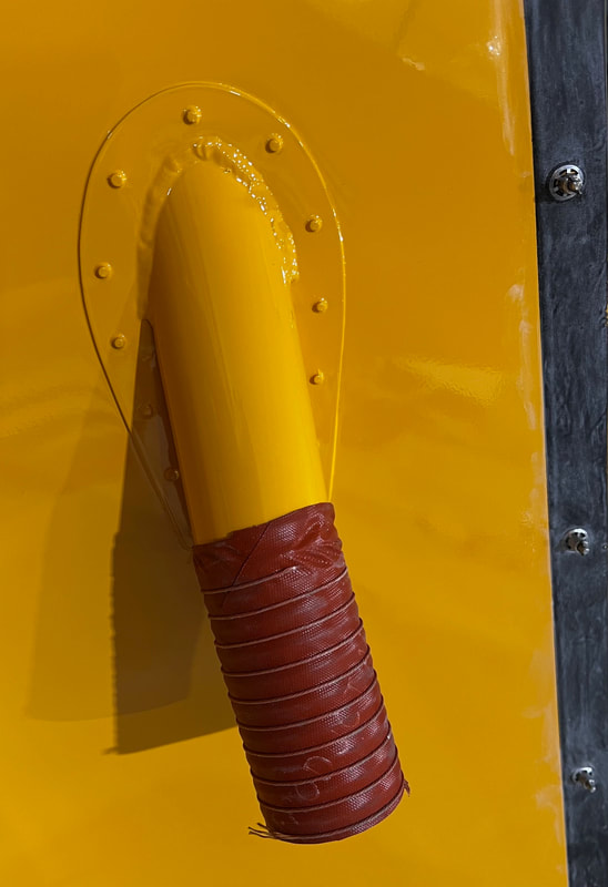
Add the short section of 2" hose to the duct. Use a bit of silicone or proseal to hold it in place.
At the very end, insert the three O-rings into the fuse box, where the three cannon plugs are plugged into it. If you do it earlier, when you inevitably remove one or more cannon plugs to do something, the O-ring will fall out and leave the premises. These are required.