INSTALATION INSTRUCTIONS
STEP 1:
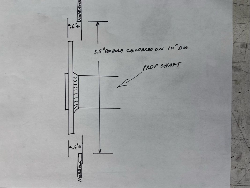
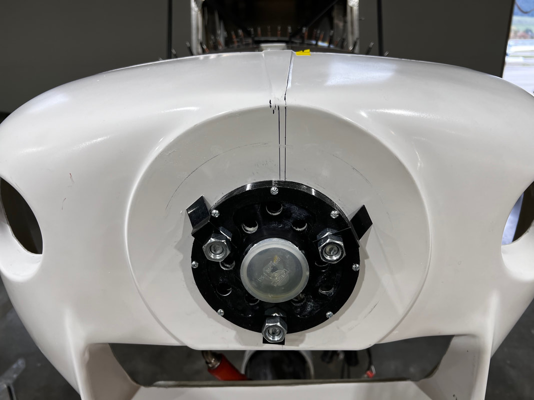
ONLY cut hole in nose-bowl (5.5" maximum diameter centered on the round approximately 10-inch circle)

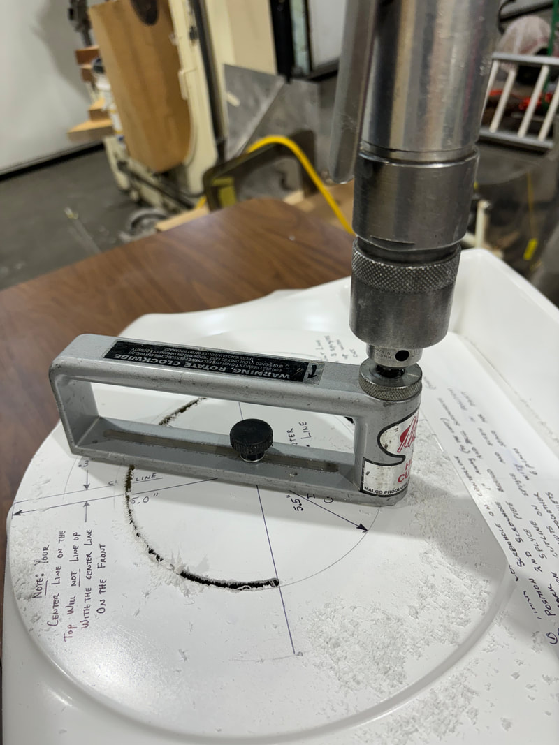
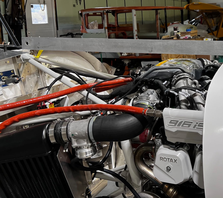
After the nose bowl has been cut with the 5.5" hole, it is ready to fit with the Skytek nose bowl positioning kit (purchased separately as an option) which positions your nose bowl at the correct position up and down in relation to your crankshaft and positioning in relation to your radiators.
If you have already installed your radiators you can cut out the FLAT part where the radiators fit. You can then trim additional fibreglass nose bowl material away until you have a 1/8 to 3/16" clearance. Make sure you KEEP YOUR NOSE BOWL LEVEL.
As a bonus the positioner kit maintains the correct angle and clearance for the spinner when using a MT Propeller. It may work with others, but I do not know.
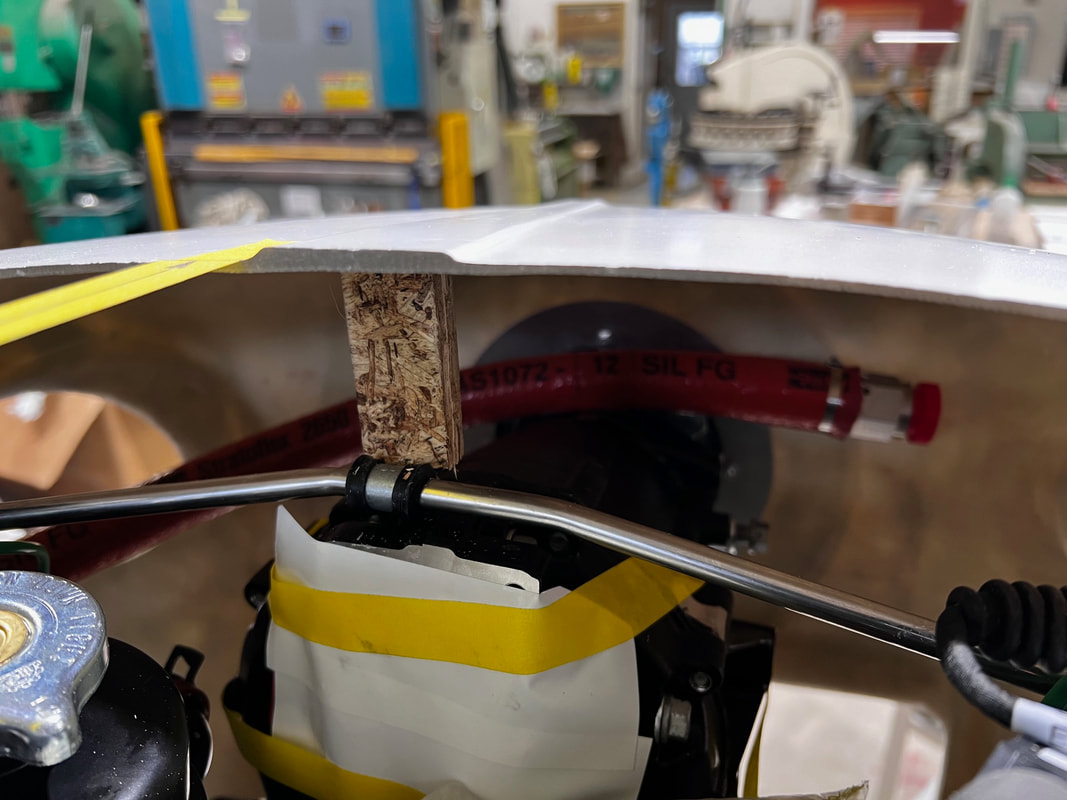
After your nose bowl is held in place, rotate to level the top. Use a straight edge to determine position and make a wood block to hold the aft edge of the nose bowl to an elevation, as shown on the next pictures.
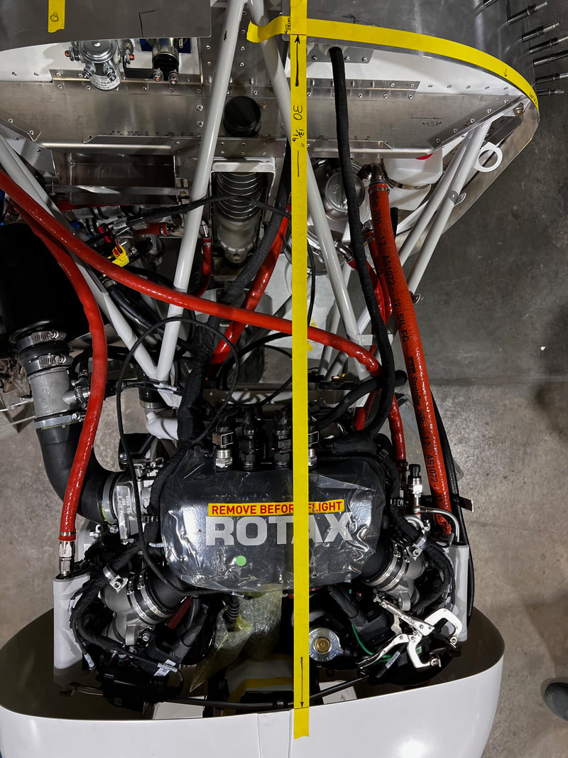
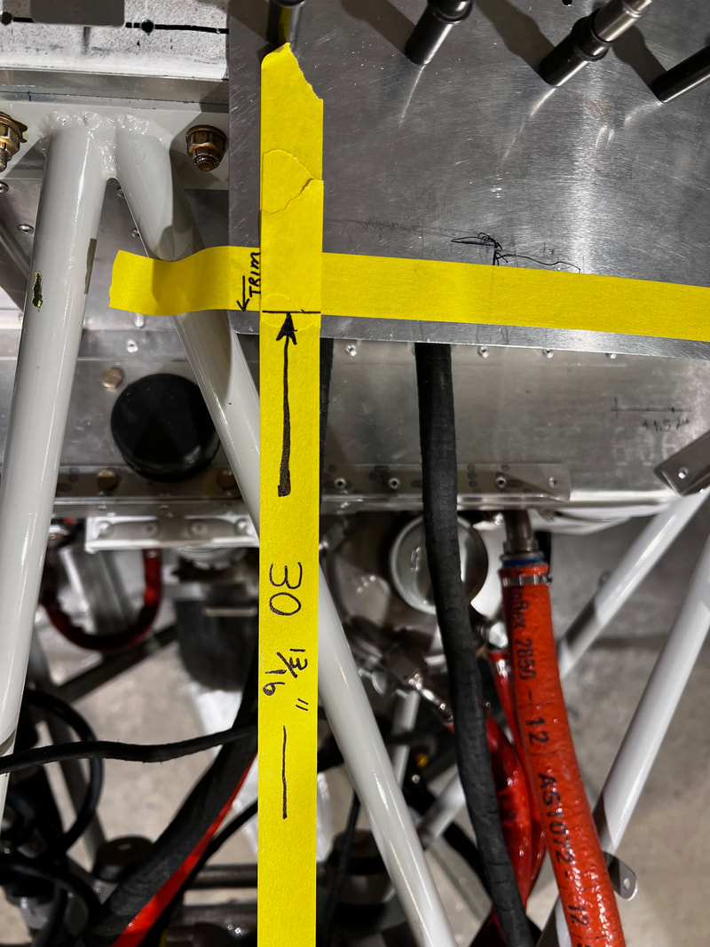
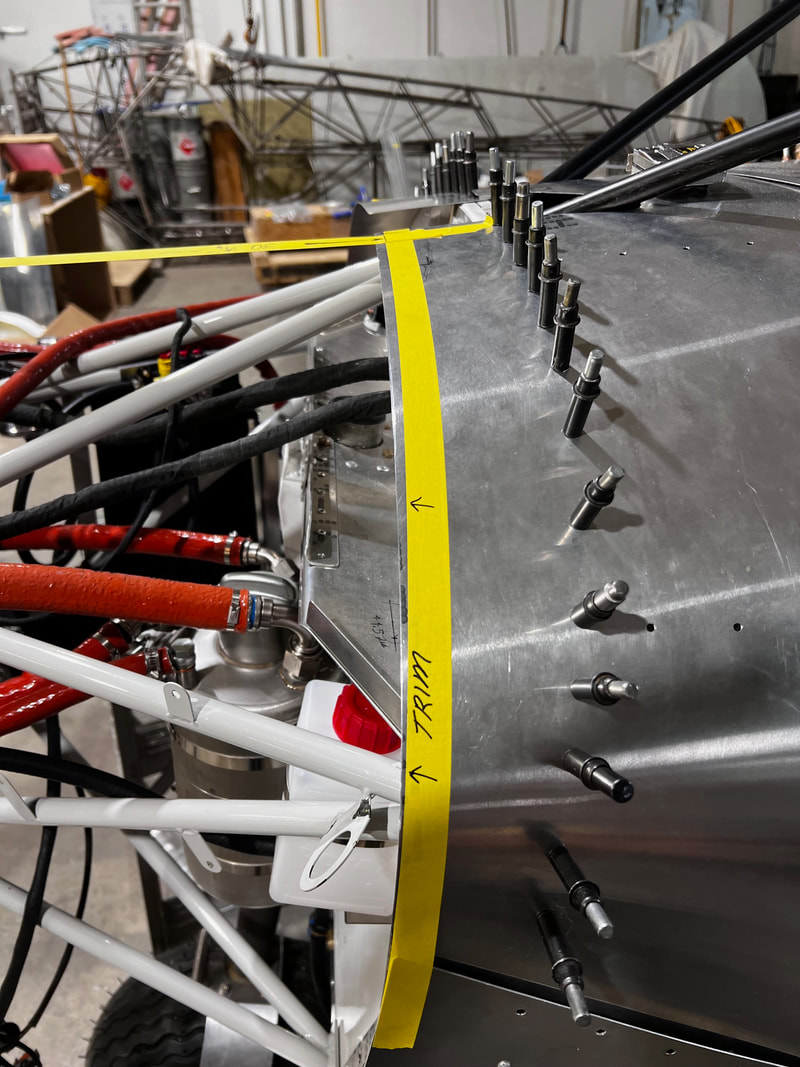
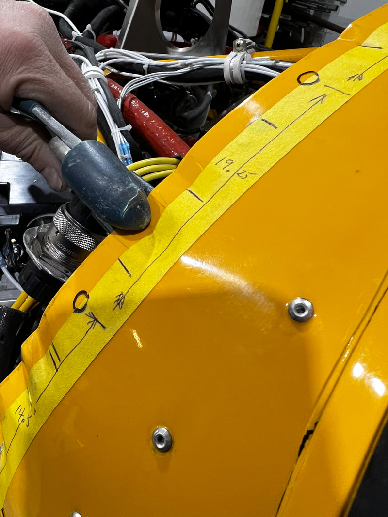
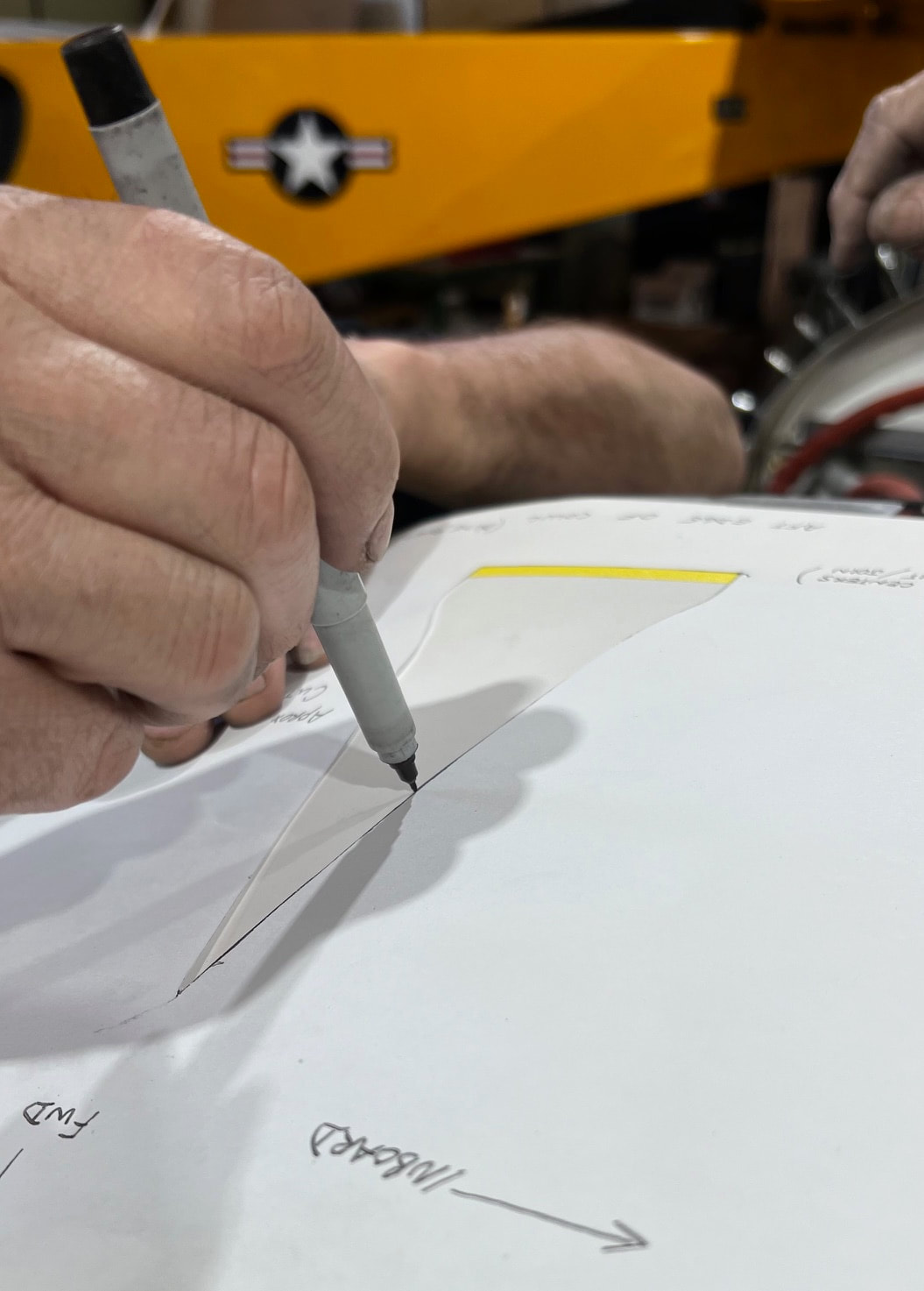
Measure and mark the top skin at 30 13/16" from the nose bowl on each side of your cutout.
Run a tape line down to the lower side skin. This is your cut / trim line.
Cut the upper skin by removing approximately 1/4" going to nothing on the outside.
On older aircraft kits you may not need to trim a thing.
Run a tape line down to the lower side skin. This is your cut / trim line.
Cut the upper skin by removing approximately 1/4" going to nothing on the outside.
On older aircraft kits you may not need to trim a thing.
STEP 2:
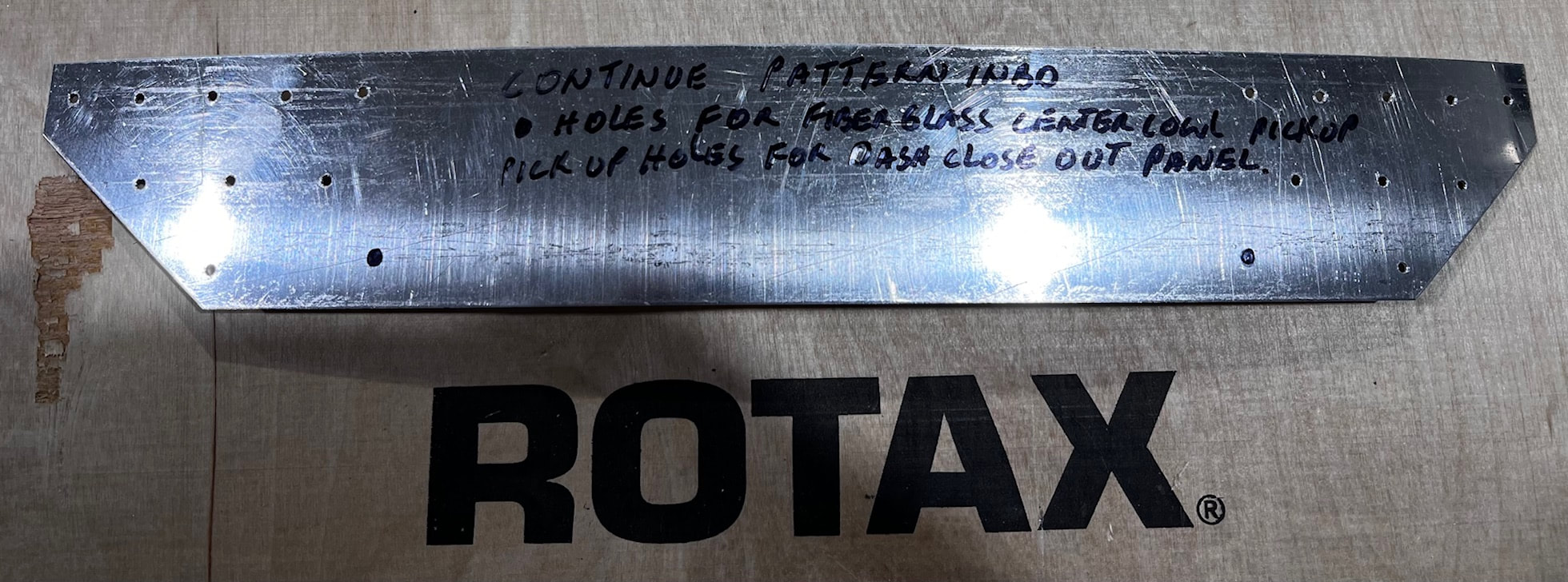
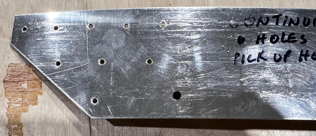
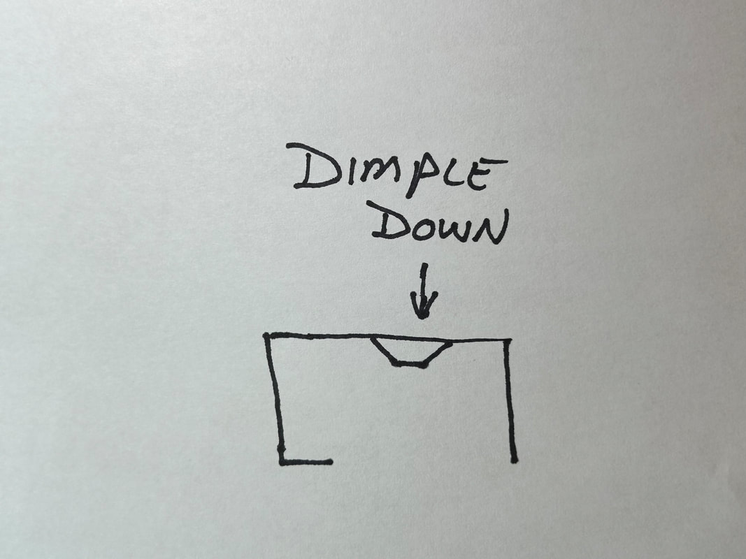
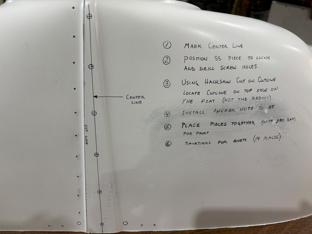
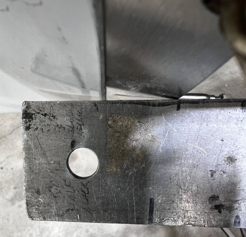
The center support doubler is to be installed at this time. A #40 hole pattern similar to the picture below should be incorporated at each end of the doubler. Pick up the existing holes for the Zenair center cover that encloses the two bars coming up out of the dash. These rivet holes should be dimpled and flush riveted. See below for details.
Below are two videos that explain how to dimple and rivet without purchasing specialty tools.
Below are two videos that explain how to dimple and rivet without purchasing specialty tools.
|
|
|
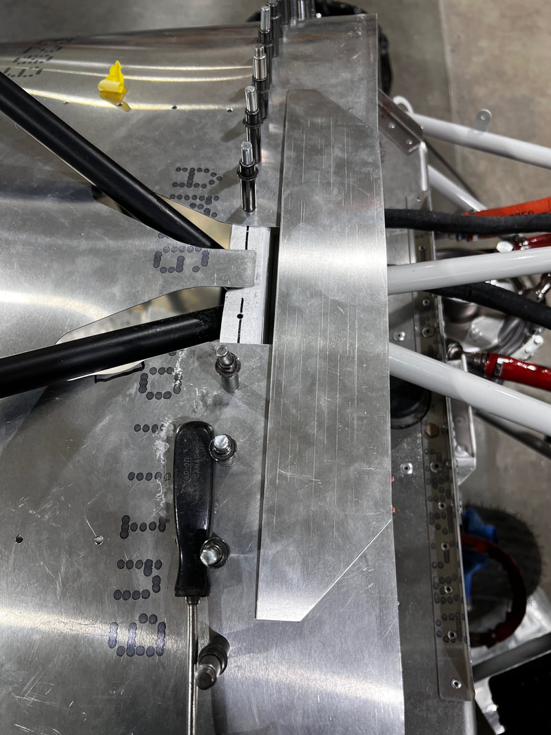
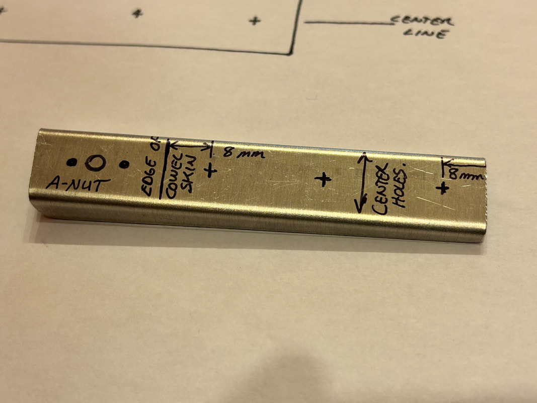
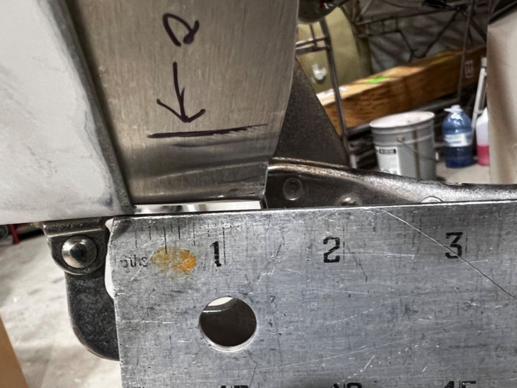
Position the reinforcement strip UNDER the top dash cowl skin on center and attach. The front narrow end should be even with the skin at a distance of 30 13/16" aft of fibreglass nose bowl when bowl is positioned correctly.
|
|
This is how to dimple and rivet without a riveting gun and equipment.
Shown is for a movable part. You will need someone to help you for a stationary part by having them hold the steel block in place. NOTE: An RV builder near you can easily assist you with this as they do this millions of times and will have the proper equipment.
Shown is for a movable part. You will need someone to help you for a stationary part by having them hold the steel block in place. NOTE: An RV builder near you can easily assist you with this as they do this millions of times and will have the proper equipment.
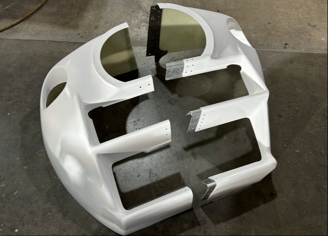
STEP 3:
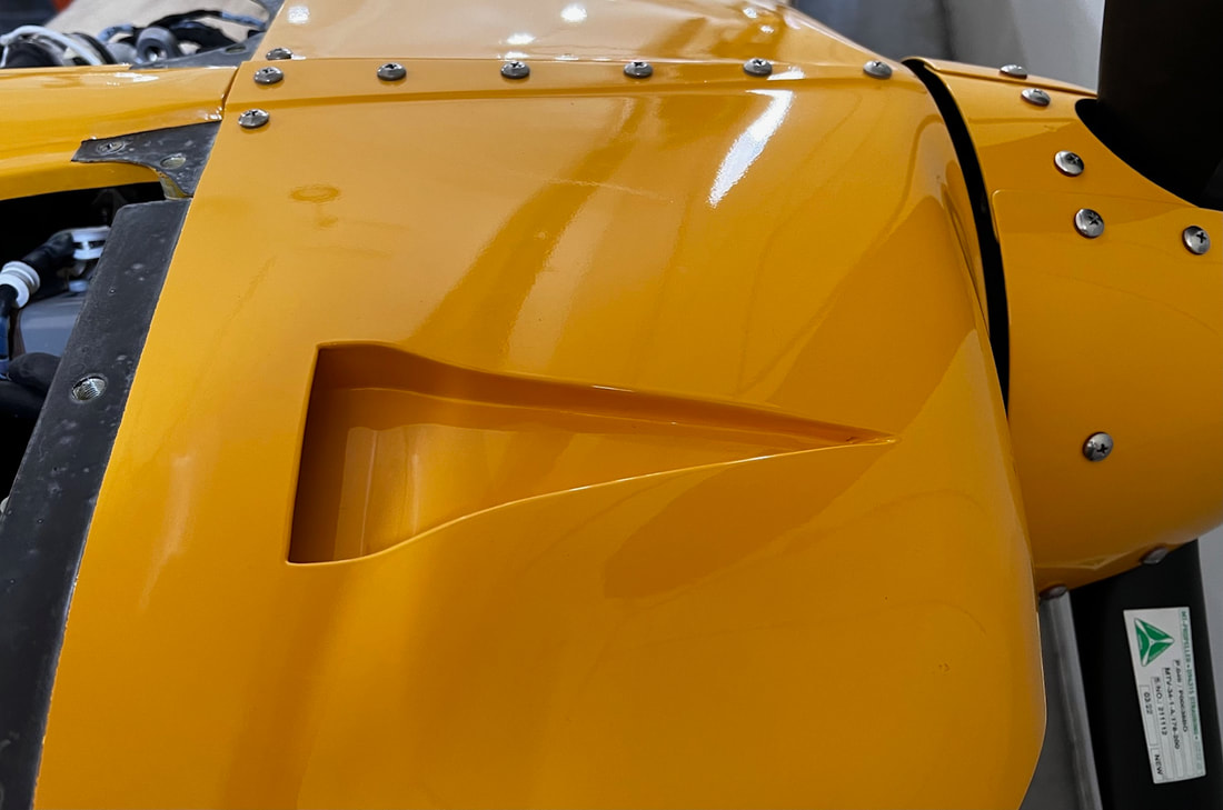
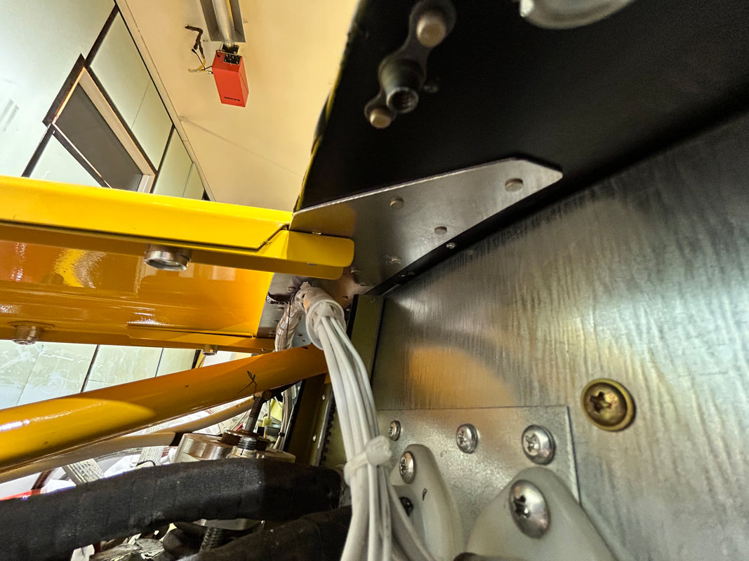
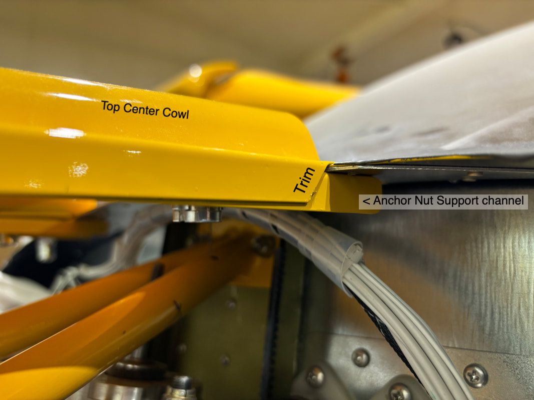
Line up the front of the fibreglass top center cowl to the nose bowl (aft-center). Clamp in place.
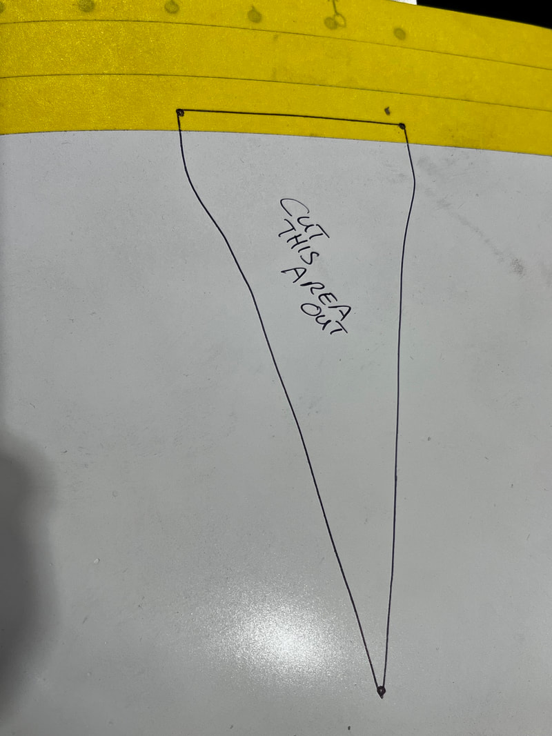
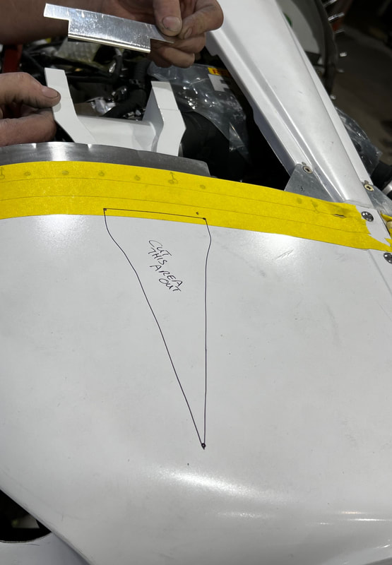
In order to clamp this in place, trim the aft vertical angles of the fibreglass top center cowl as shown below.
Again, BE SURE your top center cowl is centered before trimming.
Again, BE SURE your top center cowl is centered before trimming.
Drill the holes for the screws on both sides (Rh side shown below).
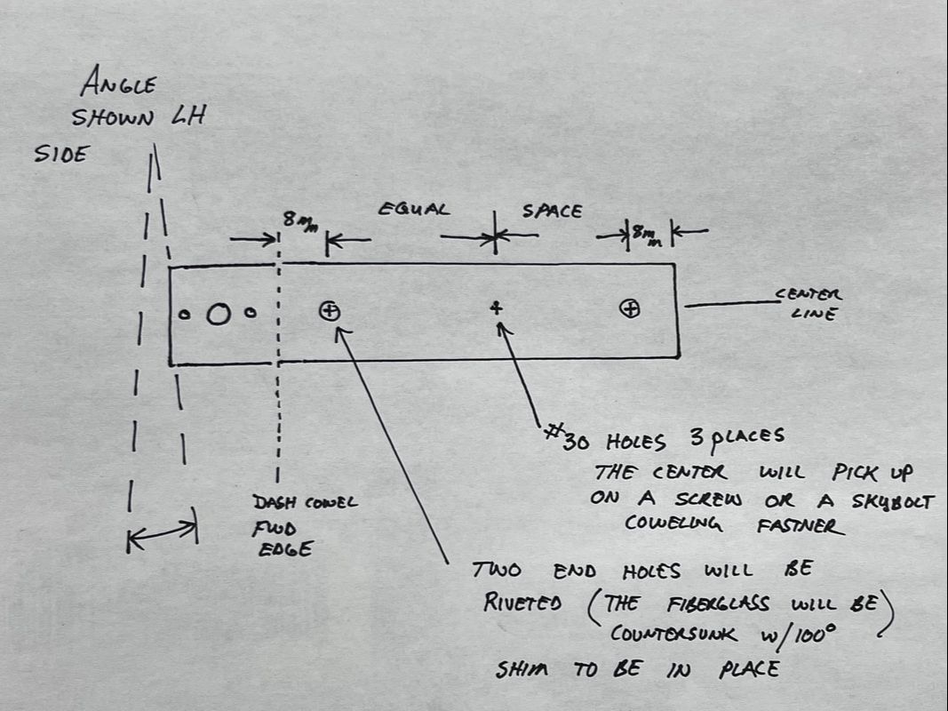
As shown in the diagram below, both anchor nut support channels have slight angles cut on the aft ends. This is a view looking down on the LH support channel.
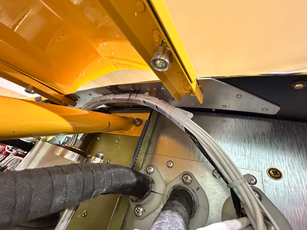
Clamp the U-channel support under the fibreglass top cowl and make sure that you allow for the wings of the anchor nut by making the U-channel stick out farther than the top center cowl as shown below.
Drill with a #10 drill bit.
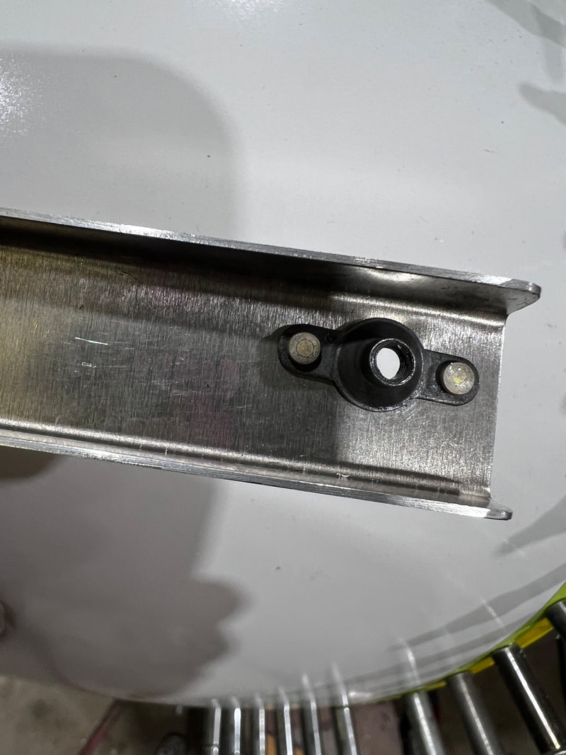
Install the anchor nut to inside of the U-channel as shown in the image to the right.
Drill with a #10 drill bit.
Install the anchor nut to inside of the U-channel as shown in the image to the right.
|
|
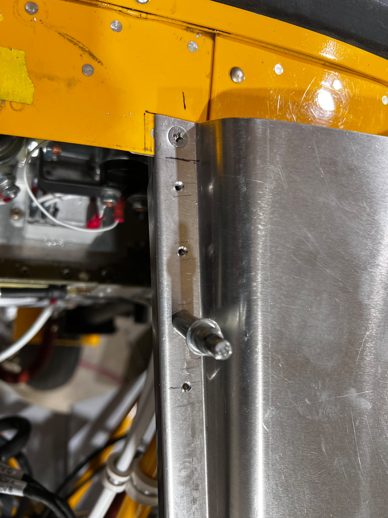
Mark and drill #30 holes in the C-channel as shown in the photos below except for center screw hole as it may be easier to pick this one up when drilling your top cowling.
Click to expand
|
|
Remove the top fibreglass center cowl from the aircraft and loosely attach the U-channels to the bottom of the fibreglass cowl with the screw into the installed anchor nut. Do not tighten, allowing for enough space for the shim to fit (Shim will be forward of the dotted line above). Clamp in place.
Back drill two #30 holes through the shim and into the fibreglass top cowl. Not the center hole as it will be picked up when fitting side cowling.
Back drill two #30 holes through the shim and into the fibreglass top cowl. Not the center hole as it will be picked up when fitting side cowling.
Countersink the screw hole in the fibreglass top cowl only with a 100-degree countersink.
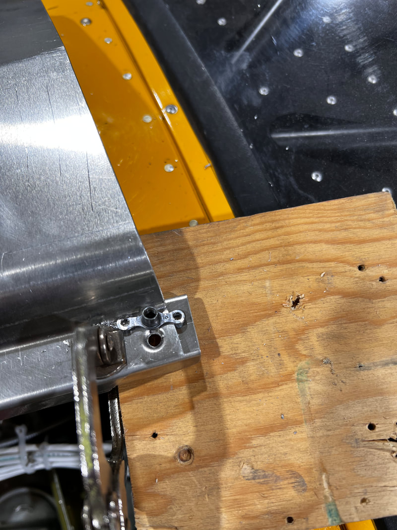
Rivet through the U-channel, shim, and fibreglass with the supplied A rivets in the two end holes only (middle hole will be picked up later with either a screw or a SkyBolt fastener during the side cowl installation).
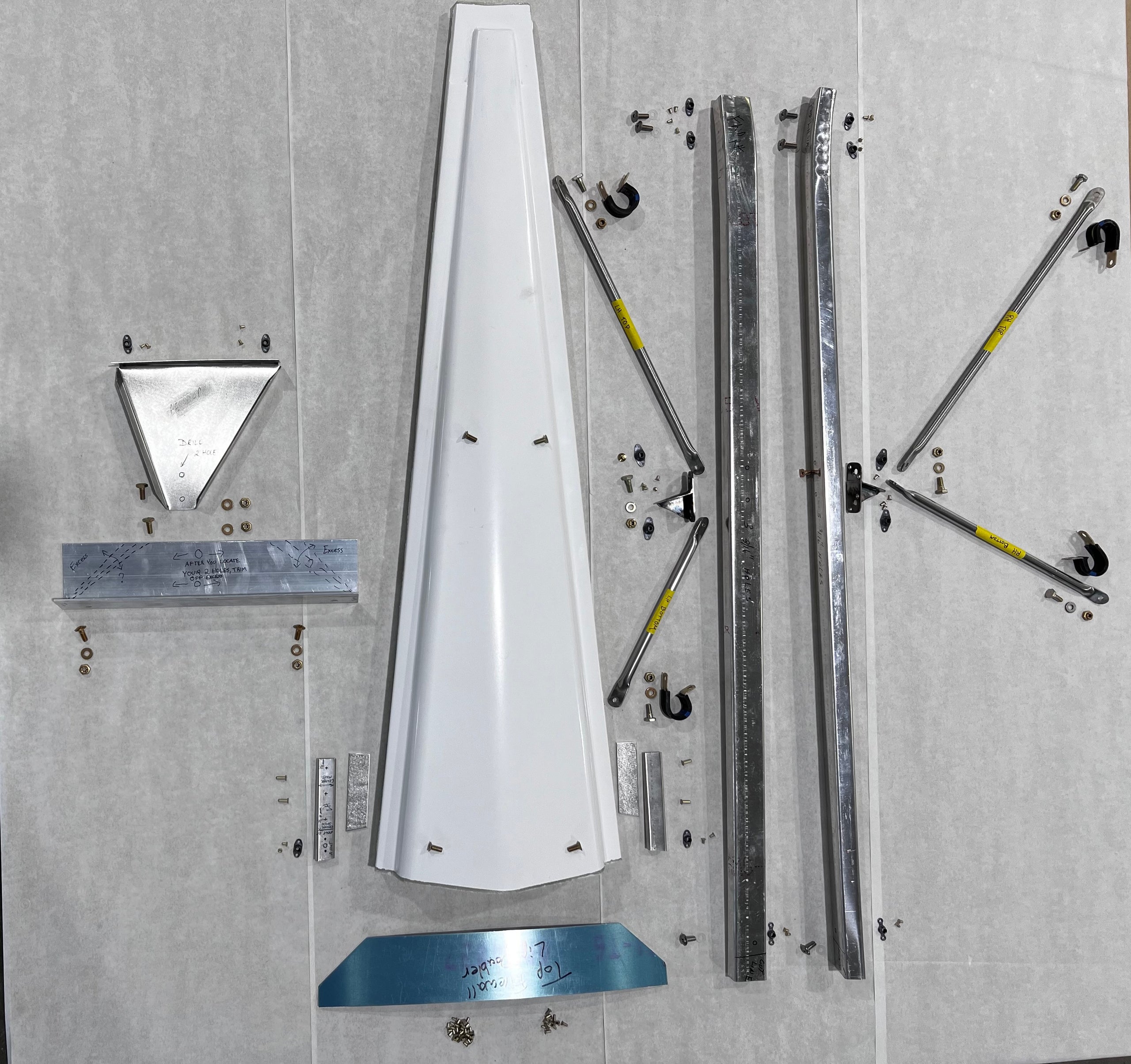
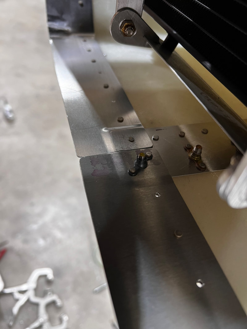
This is a view looking forward at the center support structure. The top flange on both the right and left hand sides will pick up with a screw on each and an anchor nut on the botttom of the metal flange so that it can be attached to the fibreglass center cowl section.
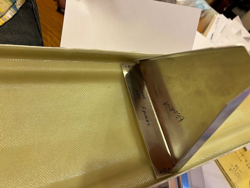
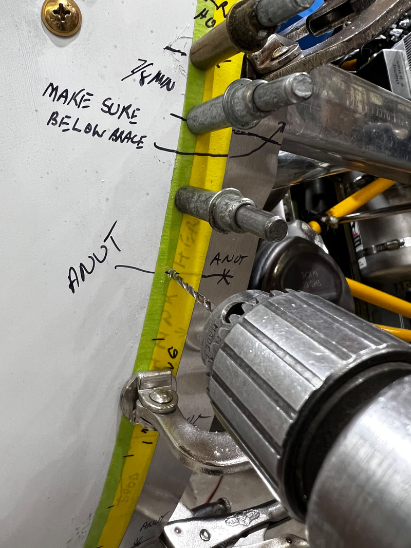
The bottom angle (2"x1.5" angle) attaches on the right and left hand bottom side with adel clamps to the engine mount. Located just aft of the engine mount rubbers.
Do this while these two parts are lightly clamped together as shown and anchor nuts and screws are holding the fibreglass center section to the top of the triangular support.
Before you drill the two holes mounting the triangular support to the bottom angle, be sure that you have clearance between the engine intake box and the top center cowl (3/8" minimum). If you do not have that clearance, you can trim the vertical flanges on the top center cowl down to 1/2" approximately of the finished height.
You may require a wedge to keep everything flat before drilling the bottom two holes in the triangular piece through the bottom angle. Once you are satisfied, drill the two holes and bolt together.
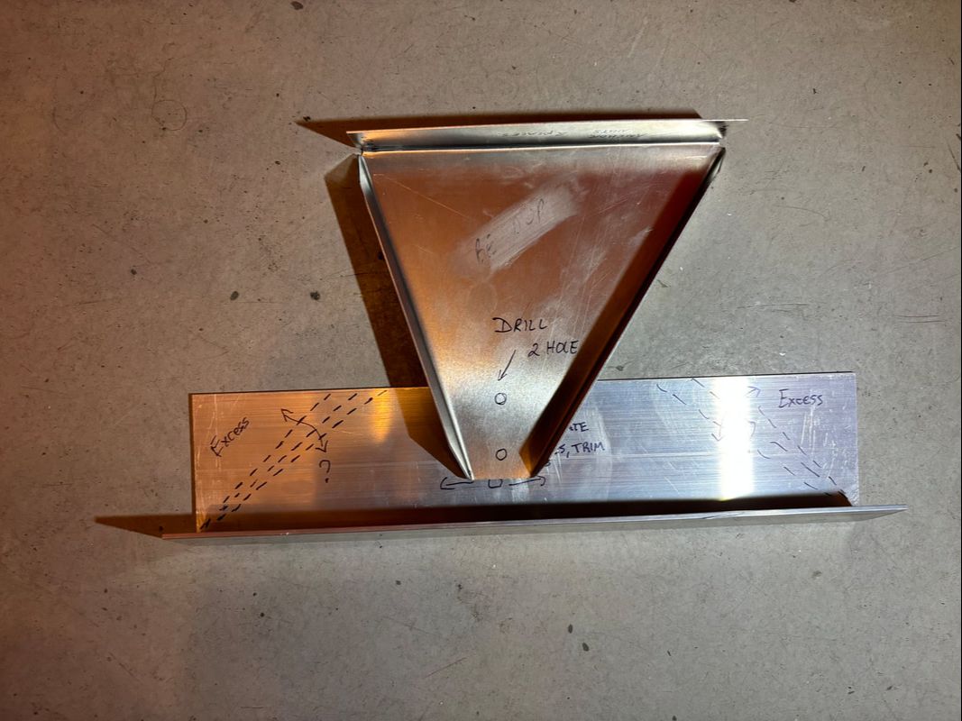
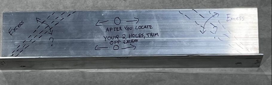
Once you have located the two holes for the triangular center support, you can trim off the excess from the corners as shown.
STEP 4:
|
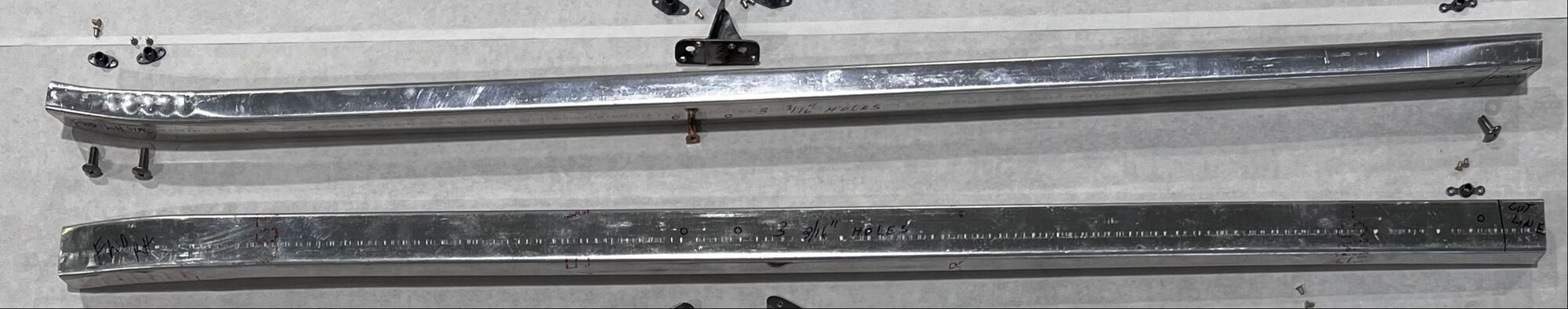
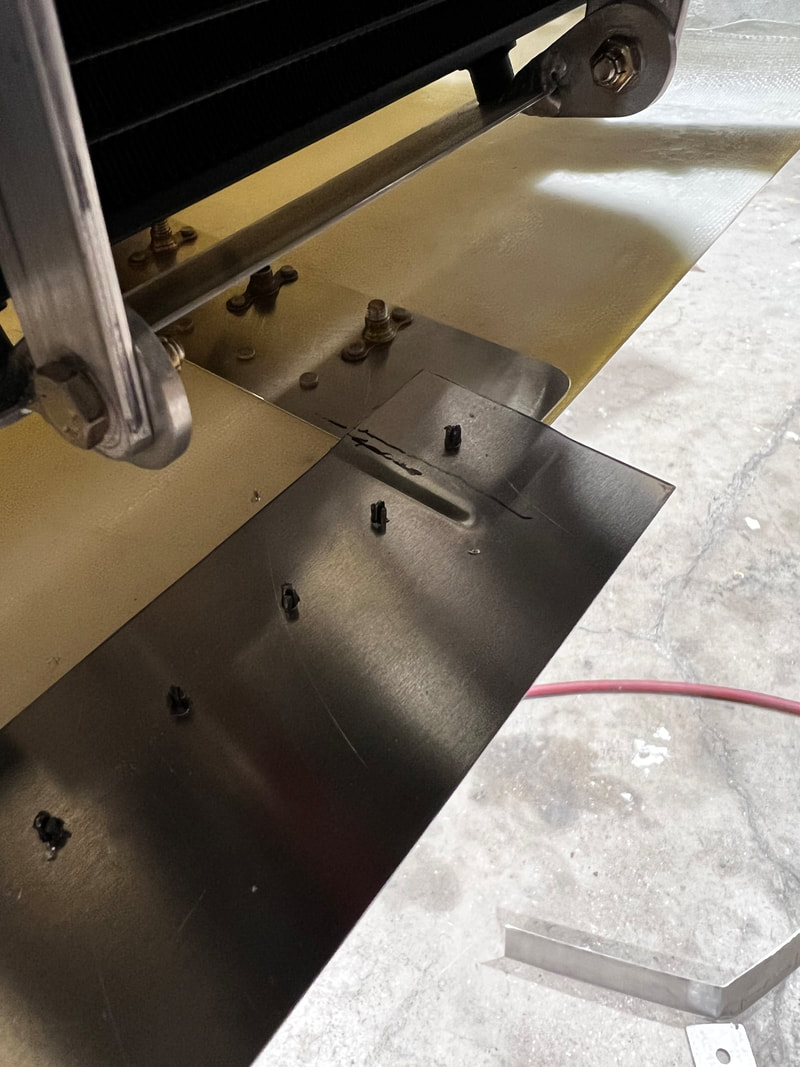
Cut the aft end off at the cut line as written on your side C-channel supports.
Drill Three 3/16" holes as marked on each side C-channel support. Dimple the two holes in the center of the side C-channel supports (2 holes each side). |
|
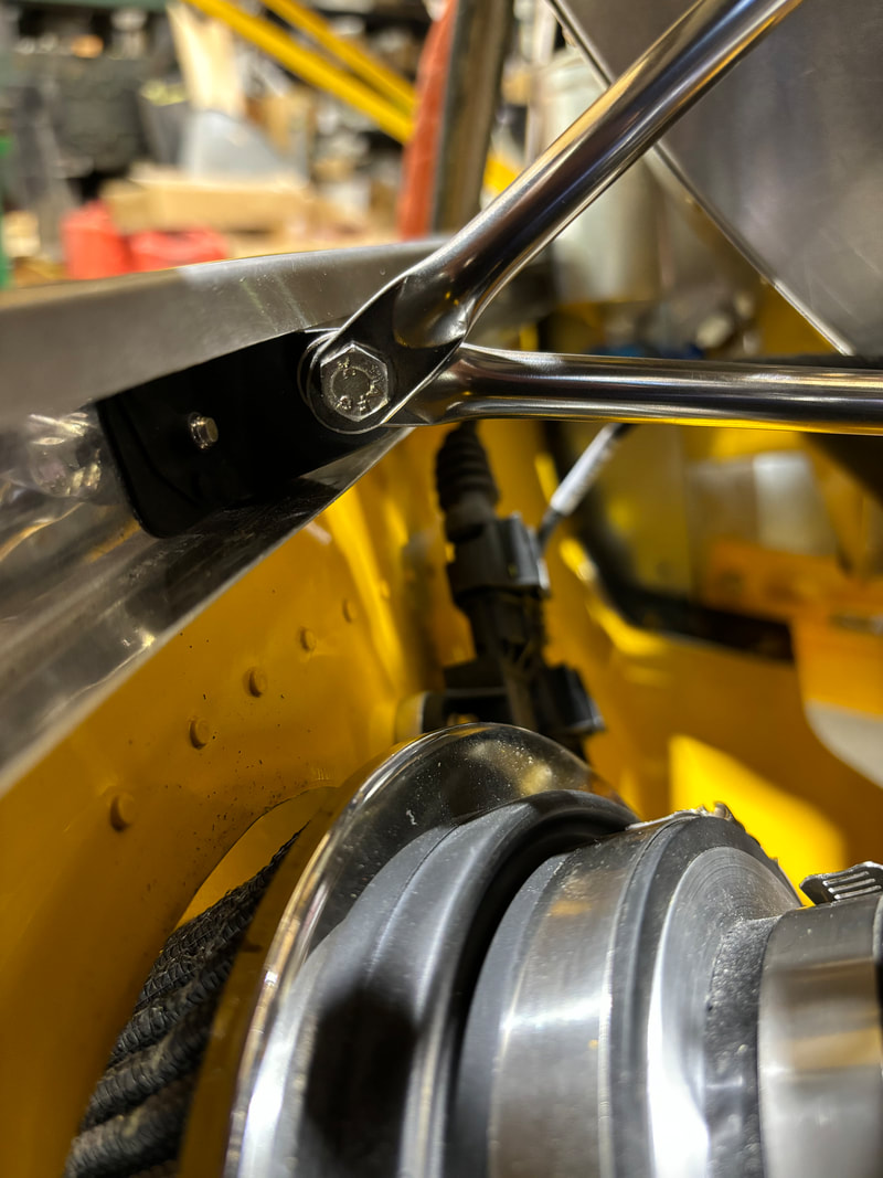
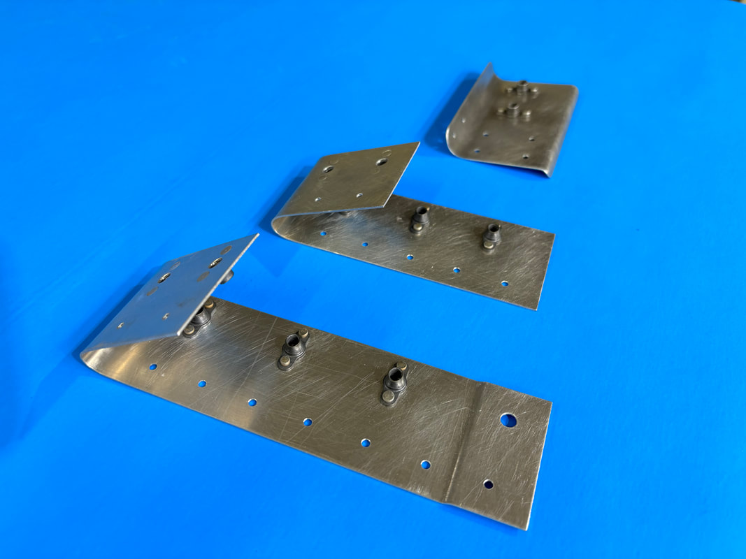
Install the two anchor nuts on each 4130 bracket, then install brackets into side C-channel supports. Install forward screw ONLY.
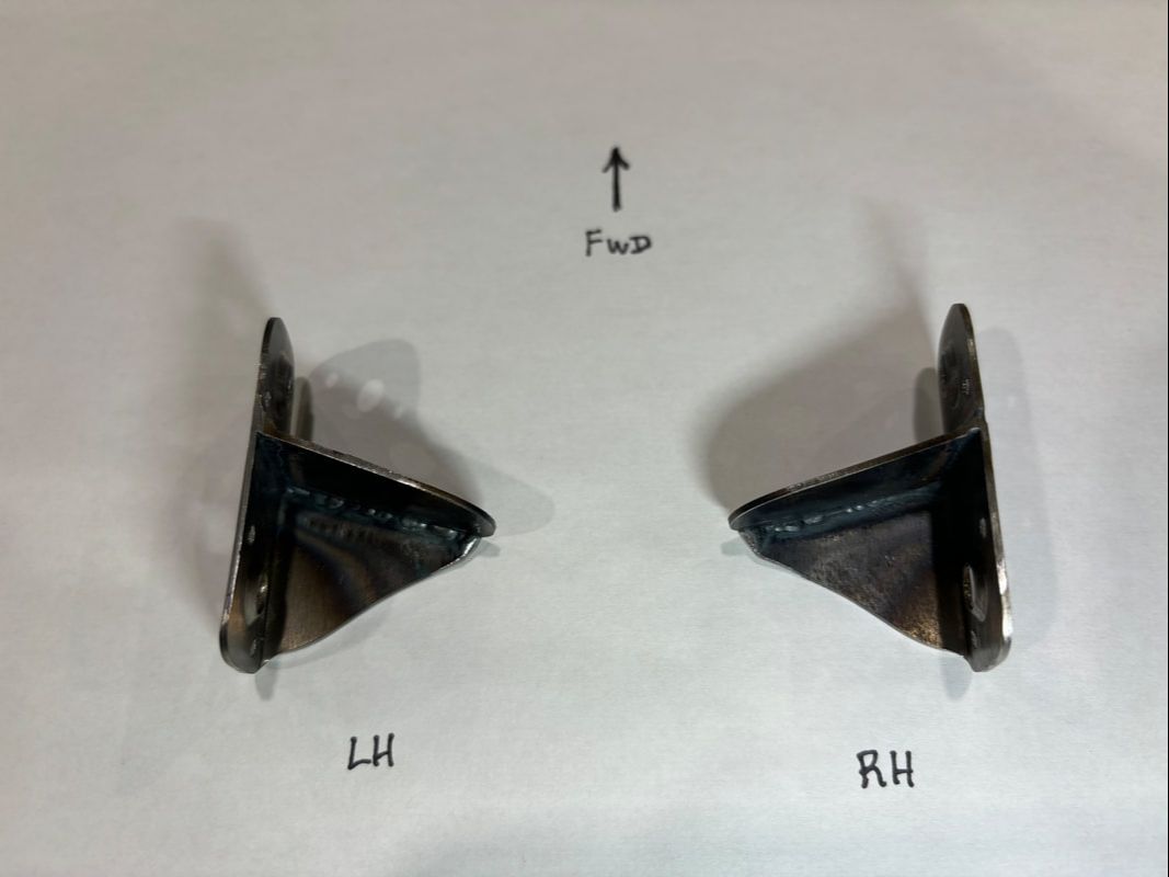
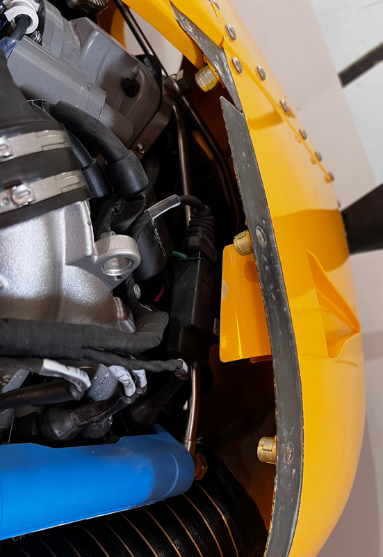
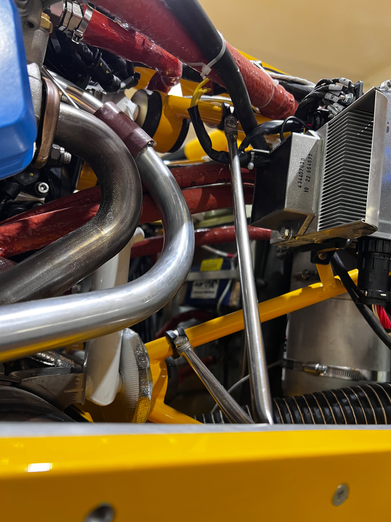
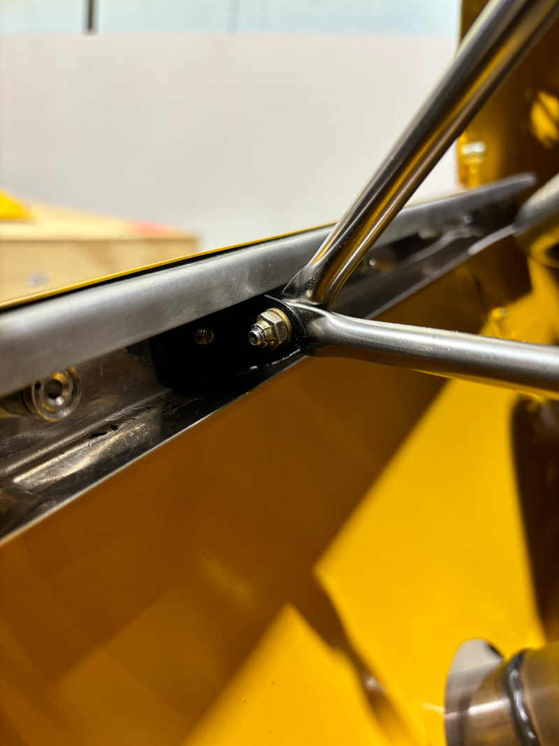
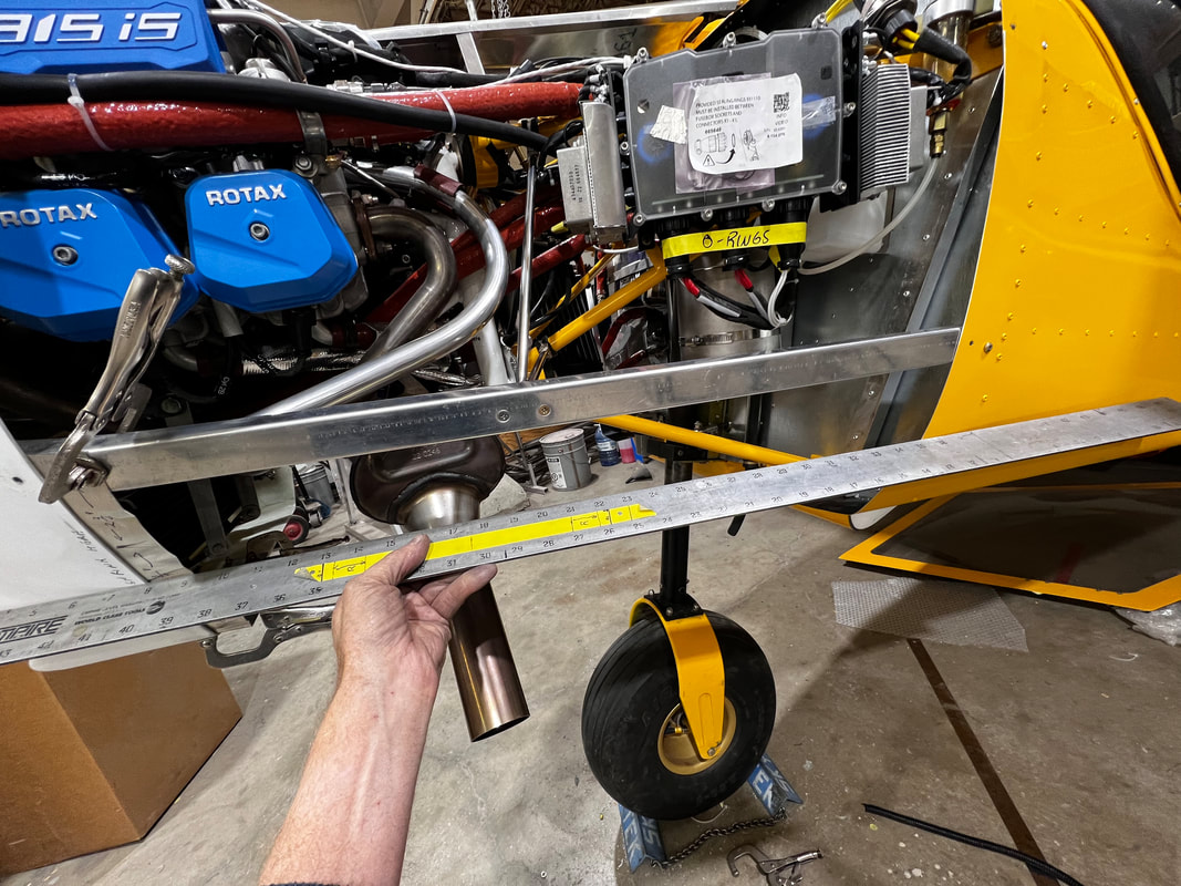
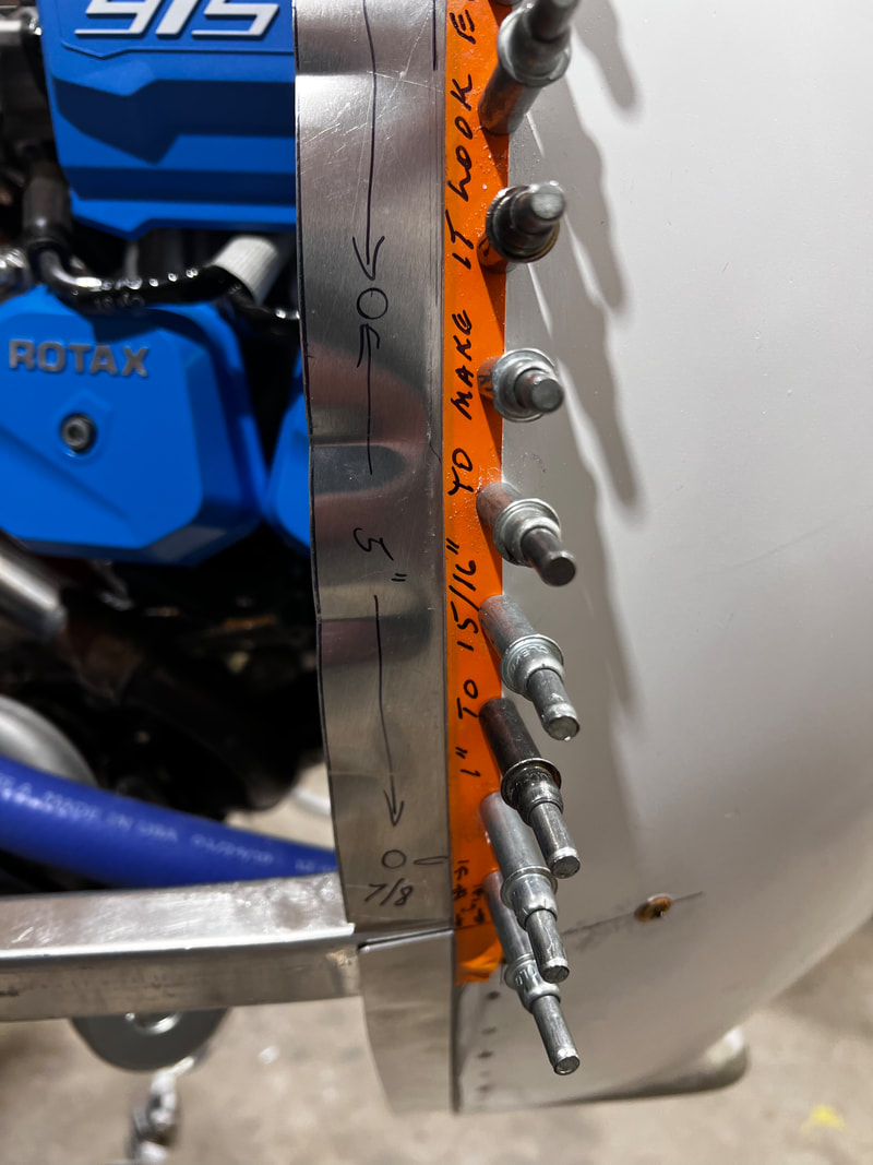
Install stainless steel support rods attaching from the engine mount to the bracket installed on the inside of the C-channel as per the photos below. The hose clamps may be slid slightly up or down the engine mount to effectively give a height of 10 LH, 10.375" RH from the bottom of the nose bowl shown in step 5.
Left-Hand Side:
|
|
Right-Hand Side: View looking forward
|
|
LH Side looking aft LH side looking aft & inboard.
STEP 5:
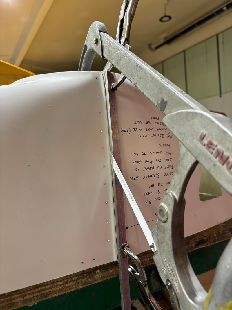
These photos show the LH side installation of the C-channels attaching to the nose bowl.
NOTE: Do the right and left hand aft sides before drilling into the nose bowl.
Attach with clamps and double check the level of the nose bowl before drilling.
NOTE: Do the right and left hand aft sides before drilling into the nose bowl.
Attach with clamps and double check the level of the nose bowl before drilling.
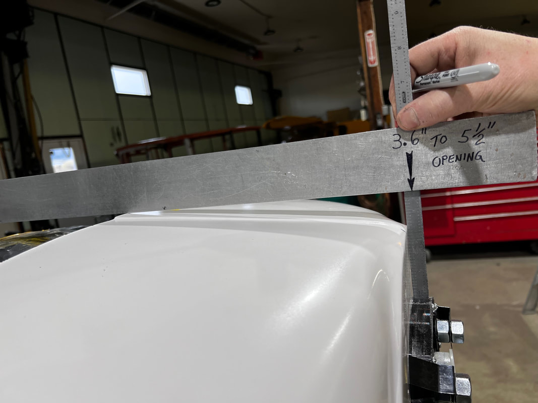
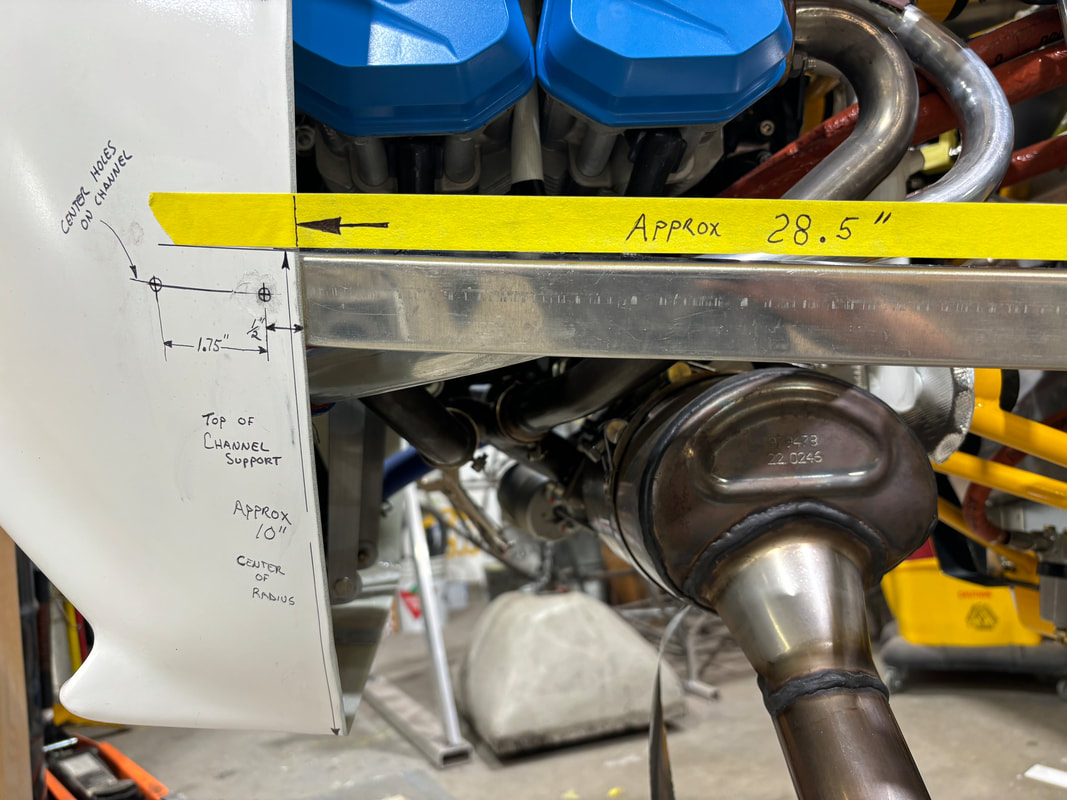
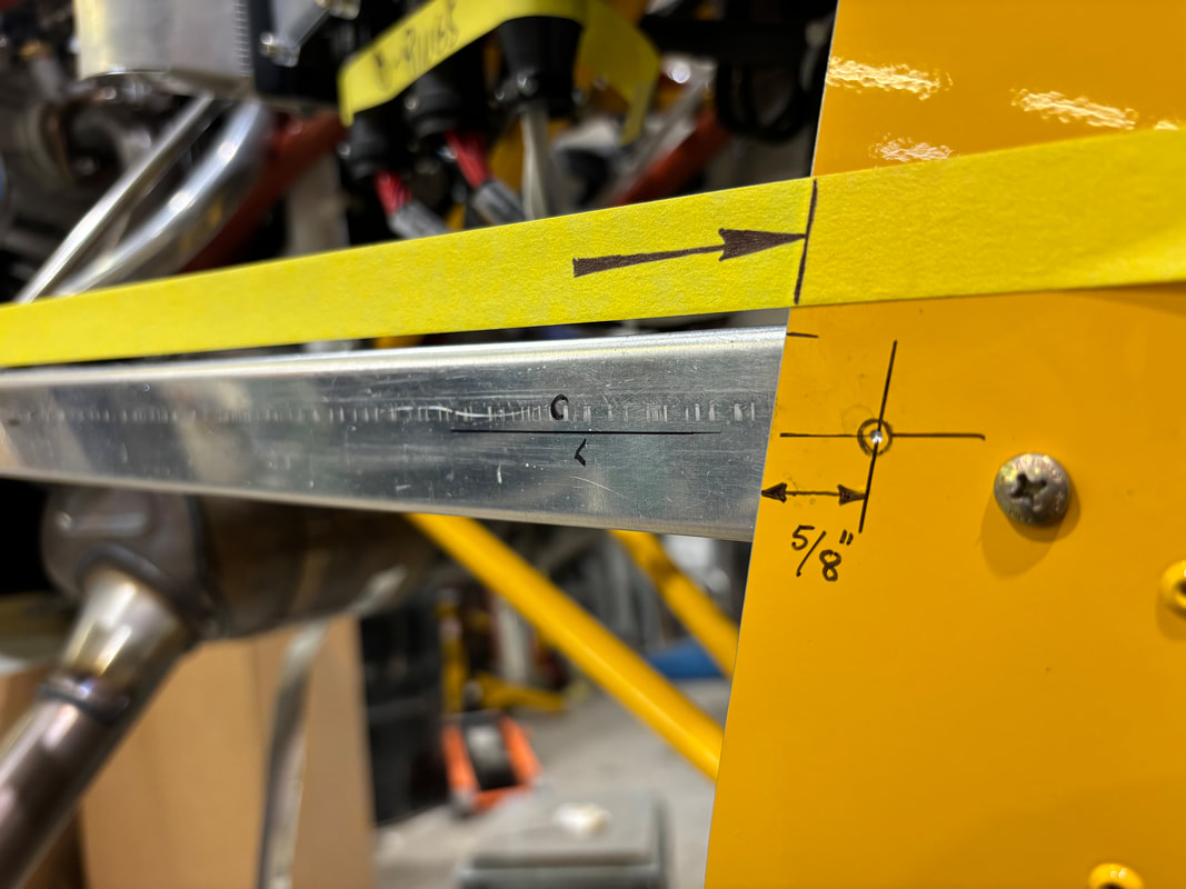
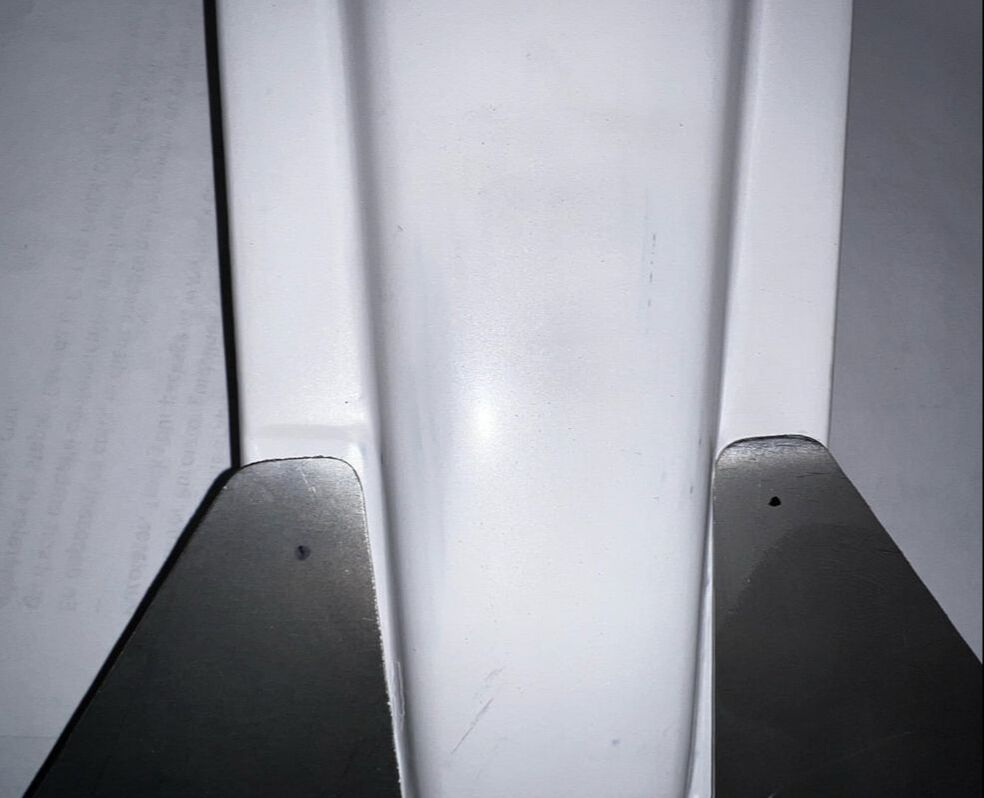
The measurement from the fuselage skin to the edge of the nose bowl (written as 28.5" in the photo below) is approximate and will vary depending on how you trimmed your front edge of your skin (Typically the right hand side is 1/8" shorter than the left side due to engine positioning). Channel position on Lh side as shown below.
Rh side should have a height of 10.375" not 10". Drill the forward 2 #10 holes through the nose bowl and side U-channels, on each side. Cleco as you go.
Rh side should have a height of 10.375" not 10". Drill the forward 2 #10 holes through the nose bowl and side U-channels, on each side. Cleco as you go.
Drill the remaining aft holes with #40 drill bit through the side skin and u-channel. Be sure not to drill too high so as to be behind the vertical flange of the C channel. This may be best done when drilling the lower cowling so you do not have to align the hole later.
Anchor nuts can now be installed in the forward two holes in the C-channels. The front of the C-channels can be cut off shorter so as to get rid of any excess material and make them fit the nose bowl better.
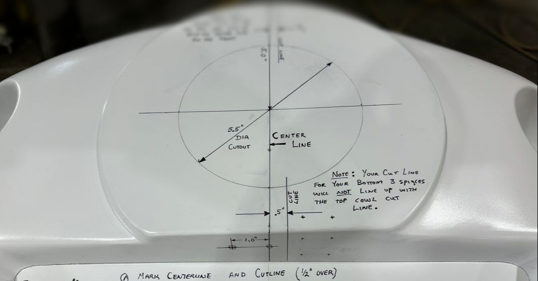
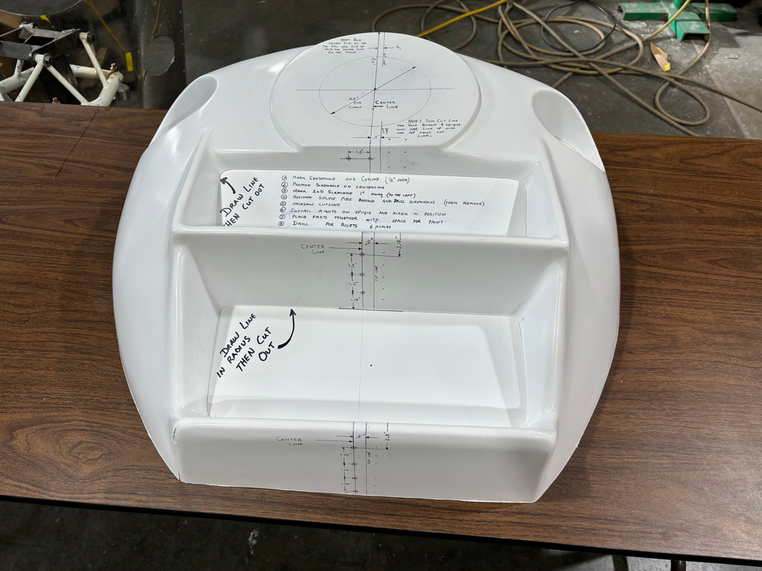
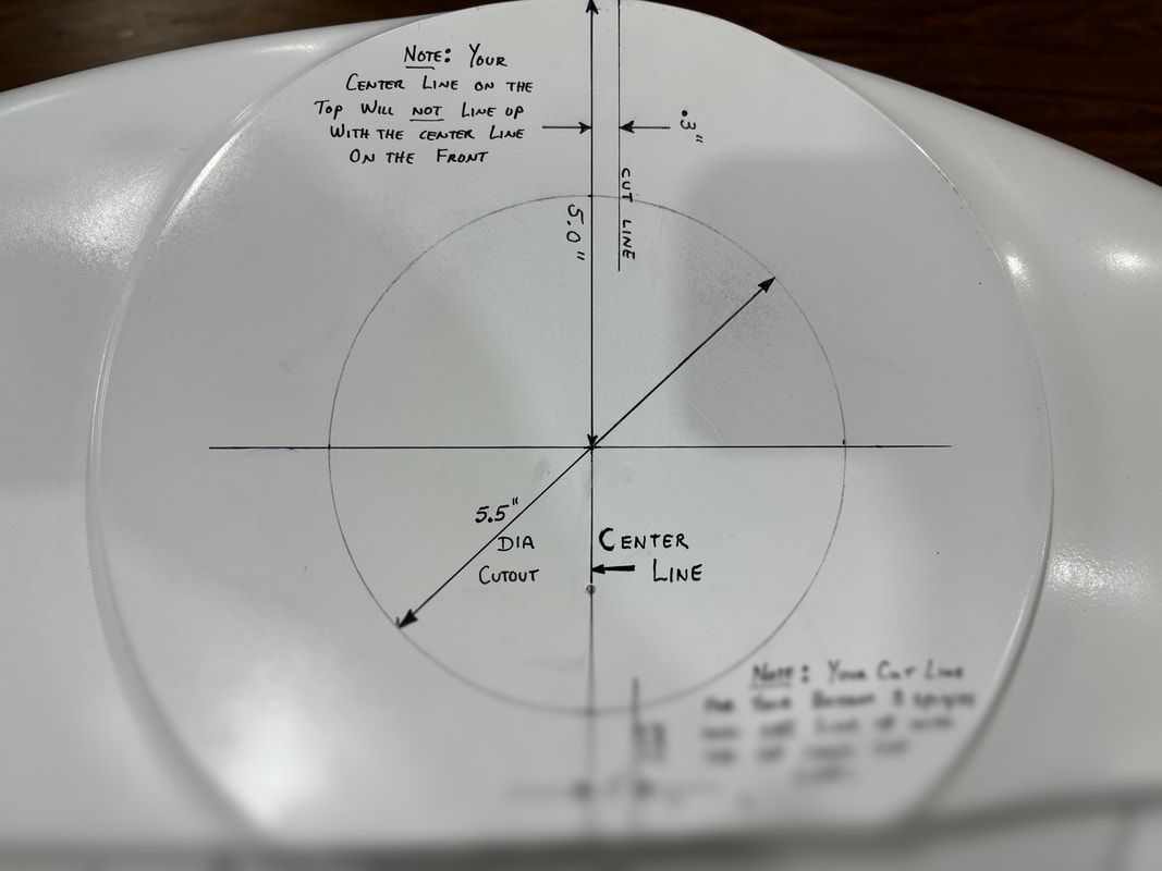
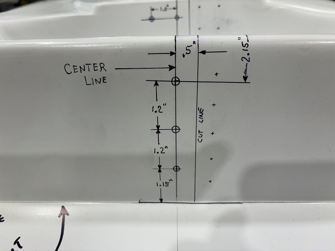
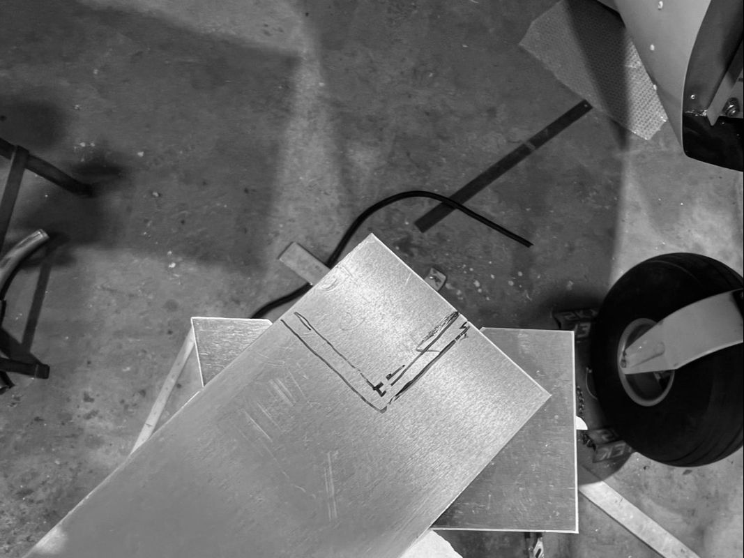
STEP 6: Splitting The Nose-BowlMark the center line of your nose-bowl from top to bottom.
Cut out the radiator air duct openings from the nose bowl. Leave as much sidewall material as possible during this step as you will be trimming it later to fit to your radiators. 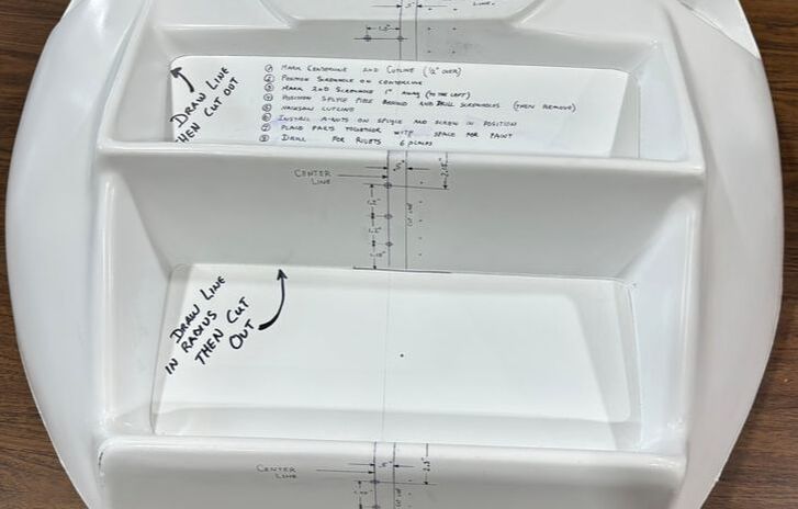
|
Cutting Tip:
To make an even finer cut, grind down the edges of your hacksaw blade to reduce the cutting width. You can also use a straight-edge as shown to make a nice straight cut.
|
|
Below the 5.5" Hole:
Mark the cut line 1/2" to the left hand side of the aircraft below the 5.5" cut out you made in Step 1. |
Above the 5.5" hole:
Above the 5.5" hole, the cut line should be marked .3" away from the center line and should then follow the left hand side of the ridge section as per the photos below. |
Click to expand.
Click to expand.
|
Click to expand.
Click to expand.
|
Once your cut line has been clearly marked and you are satisfied that your lines are straight and neat, cut using a hacksaw or saw of your choice.
STEP 7:
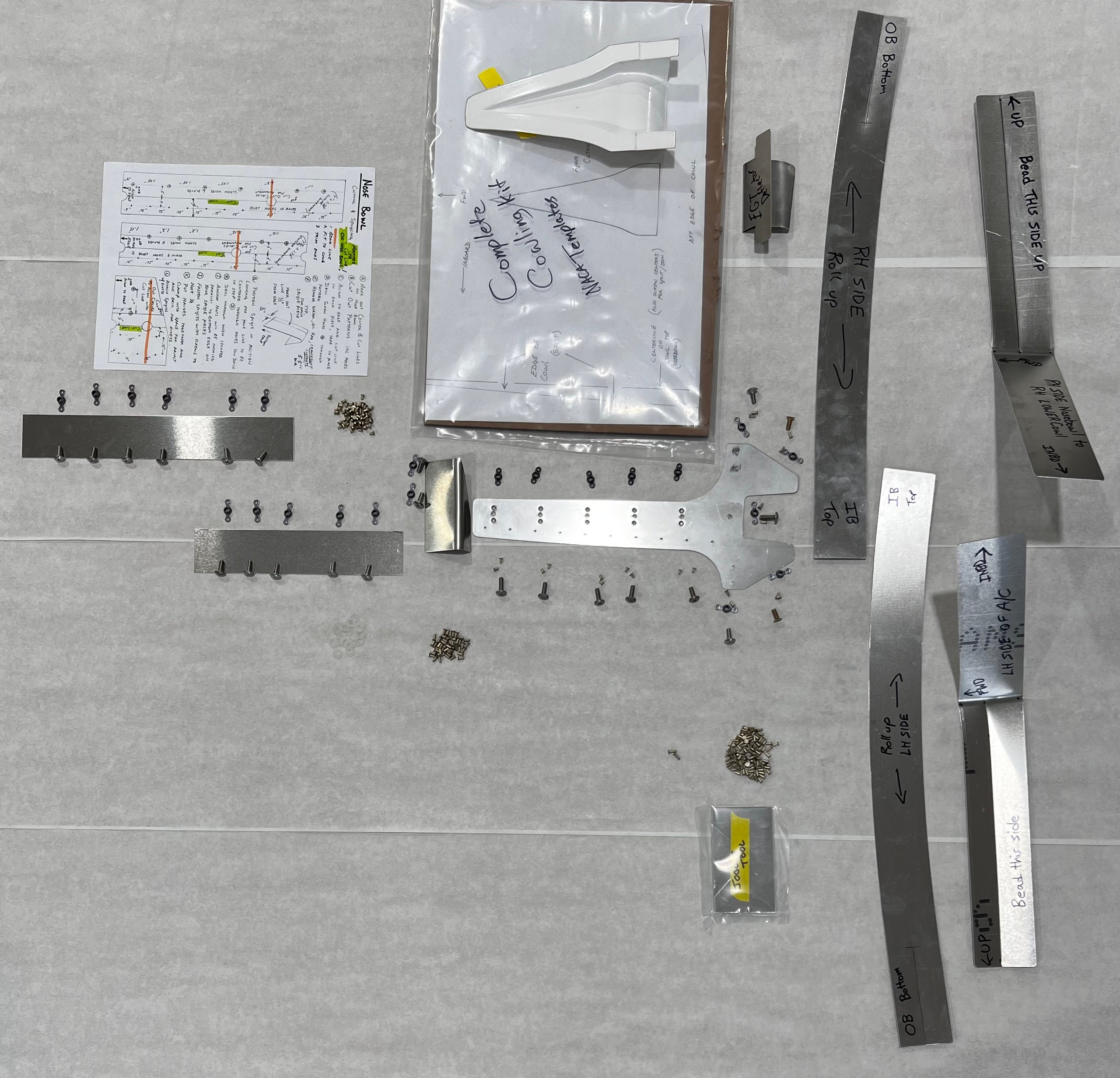
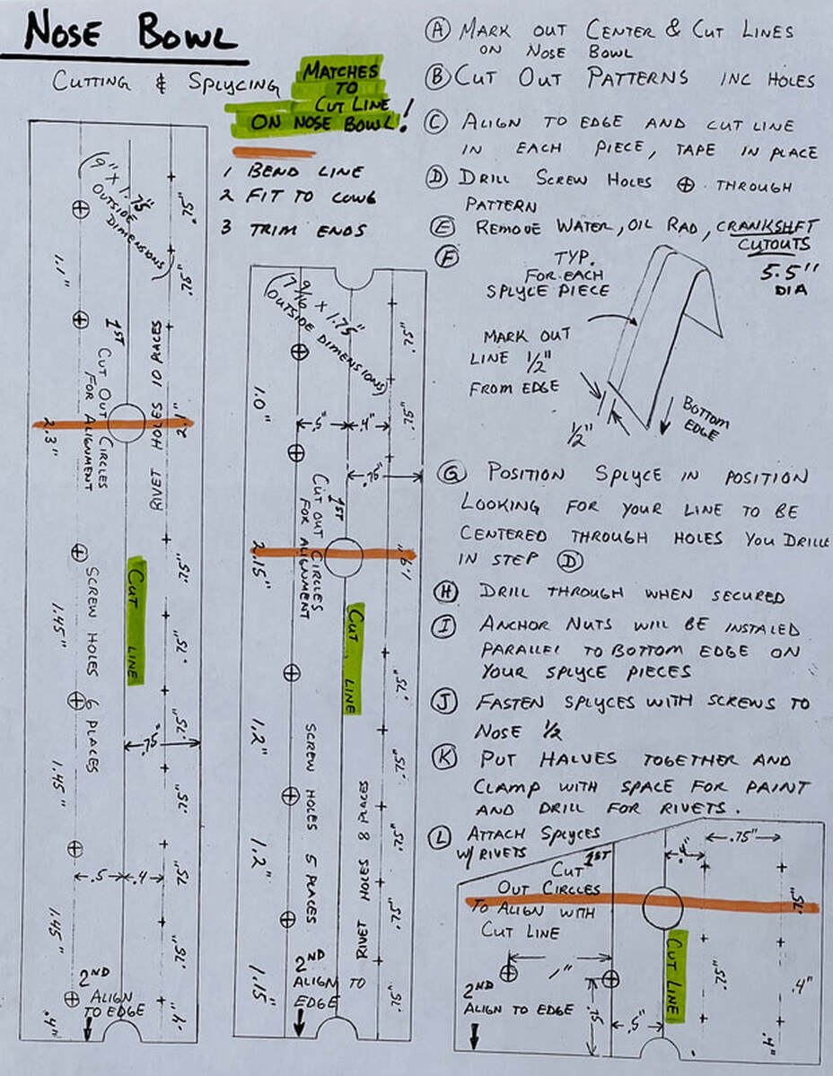
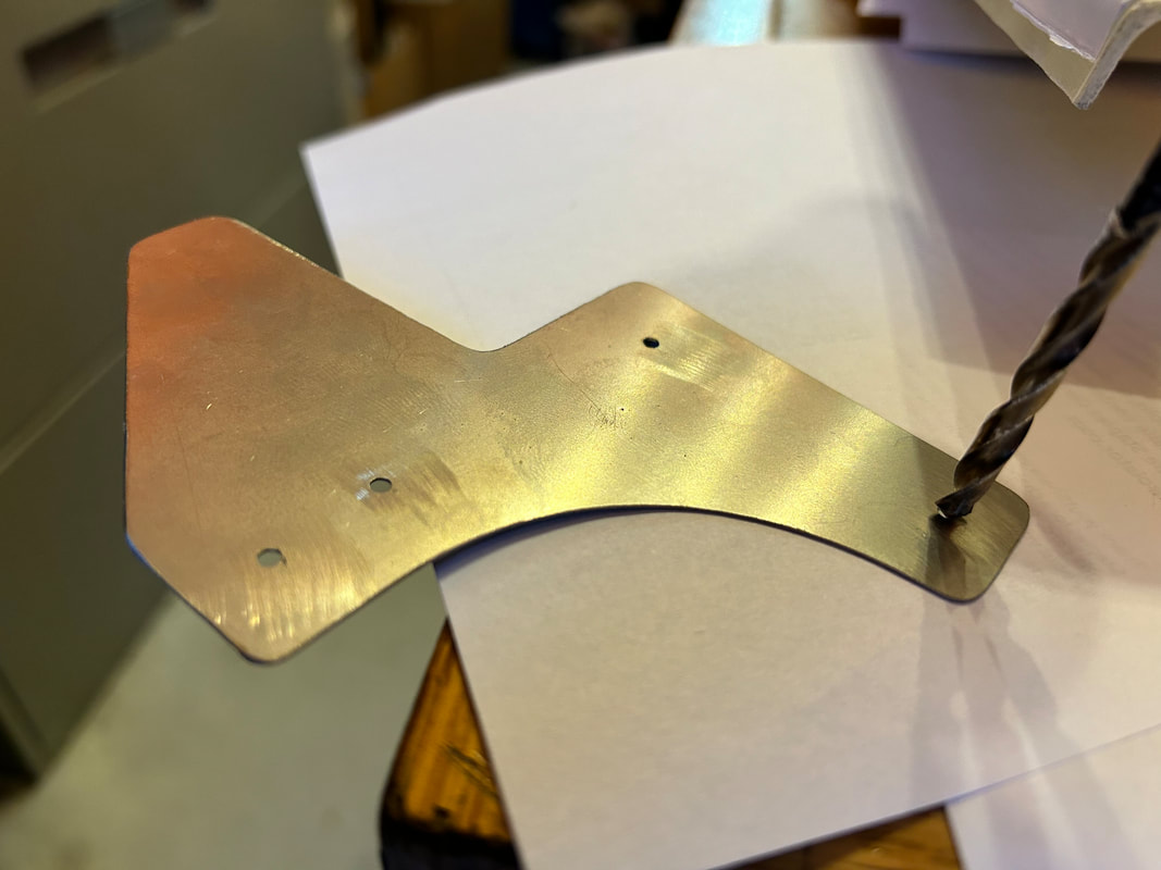
Bend and fit the nose bowl splices to the nose bowl as shown in the images below. You will trim them to length and drill in the next steps.
|
|
Using the patterns provided in your kit, follow those instructions to mark, cut, drill, and fit your nose bowl splices.
NOTES:
- The large holes under the orange lines shown below are to be cut out on the paper ONLY and are a guide for aligning the paper pattern up to the bends on your metal splices.
- On step I, install the anchor nuts.
- Countersink all holes in fibreglass with 100-degree countersink to allow for flush rivet installation. Do not over-countersink.
|
The following image shows the left layout above as drawn on the nose bowl.
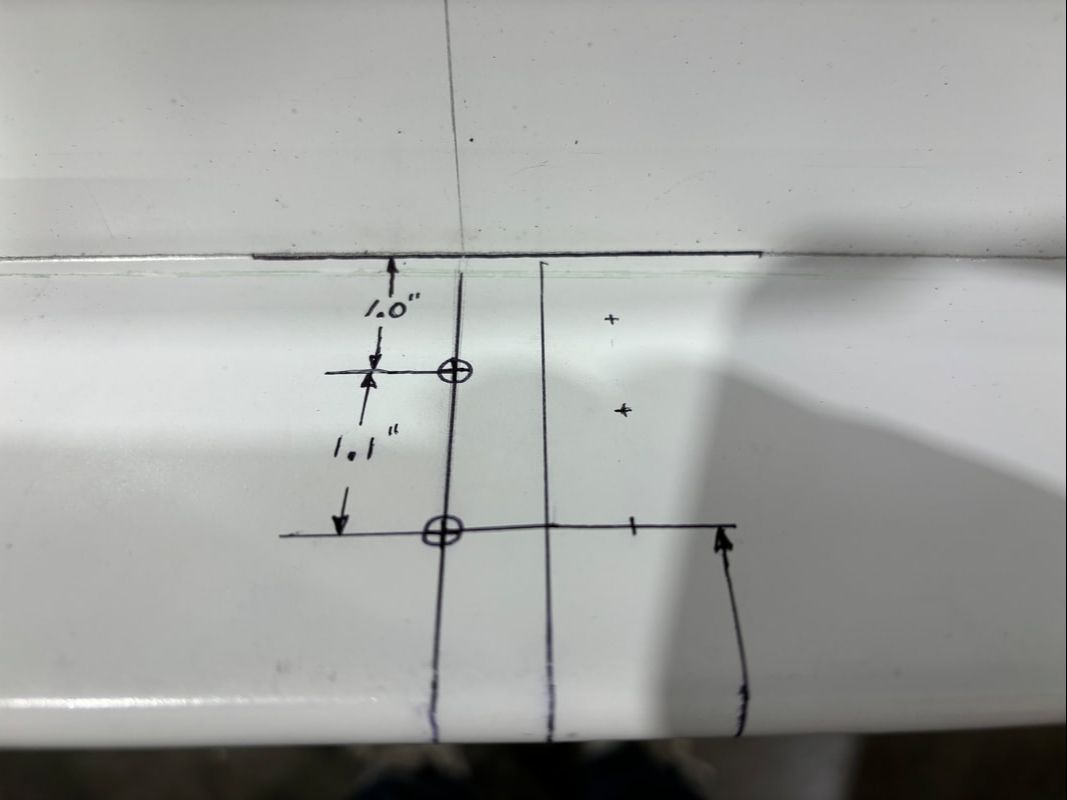
View looking at the bottom of the nosebowl.
|
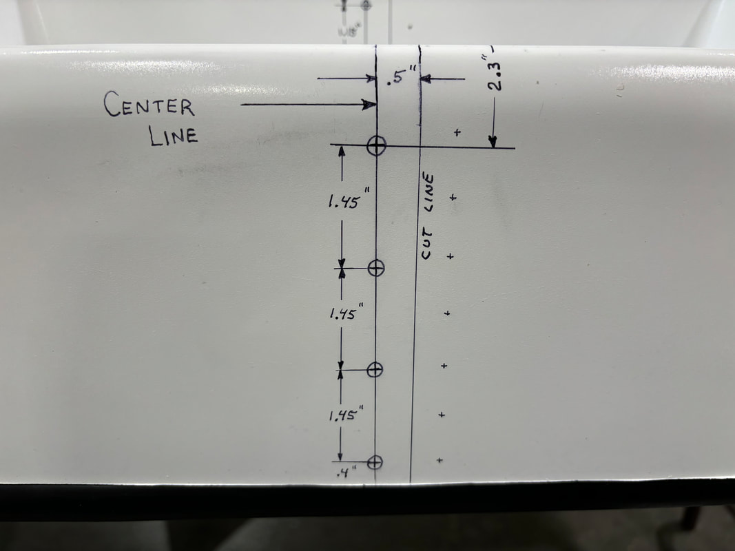
The following image shows the middle layout above as drawn on the nose bowl.
|
STEP 8:
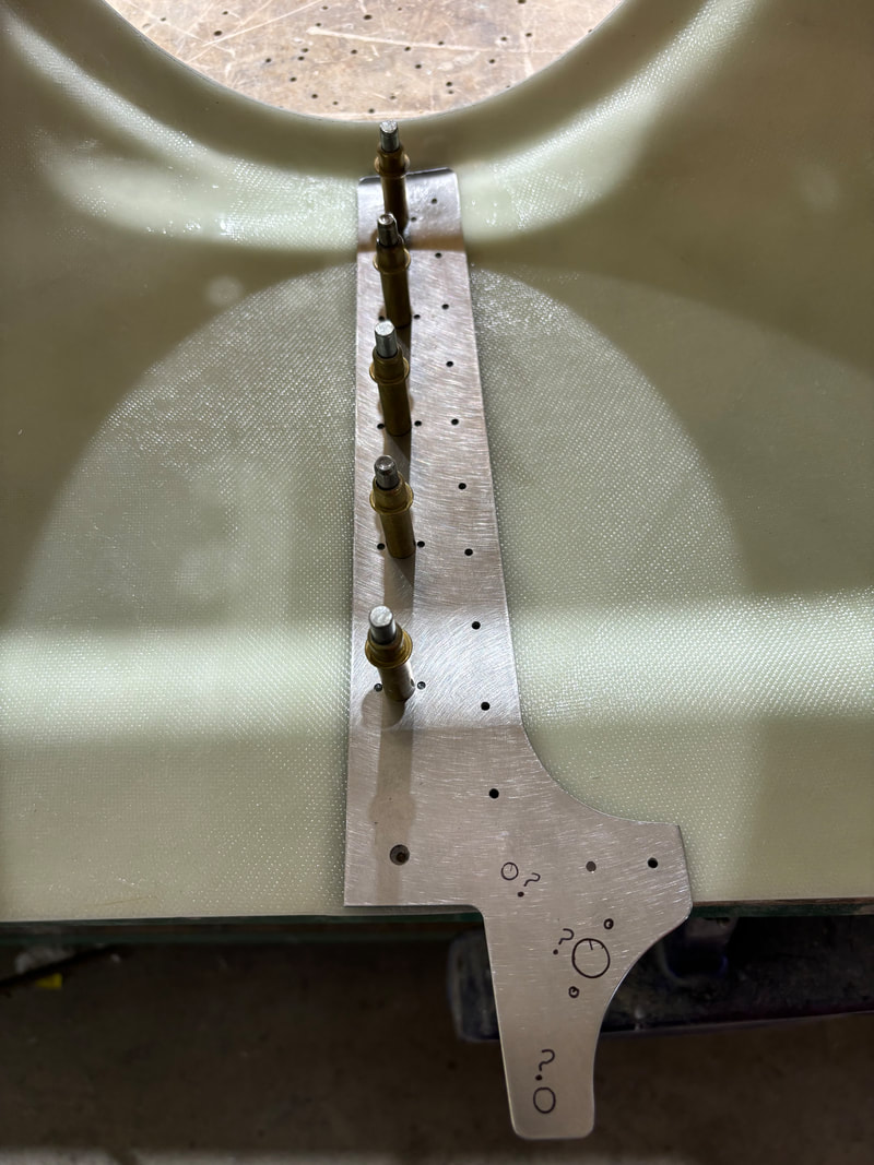
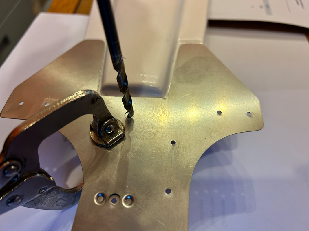
Using the center line on the top of your nose-bowl, align the anchor nut center holes in the stainless steel piece on that line.
Drill #10 holes using the stainless steel piece as a guide.
Drill #10 holes using the stainless steel piece as a guide.
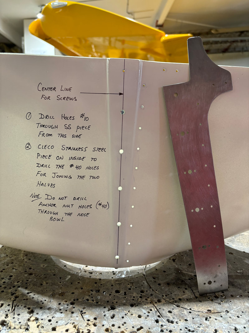
Install anchor nuts on the stainless steel piece and then screw to the nose bowl cowl half to hold in place.
Set your gap between the two nose bowl halves, clamp, and drill through the stainless piece for rivets.
Again, countersink fibreglass for flush rivets. Do not over-countersink.
Rivet in place.
Set your gap between the two nose bowl halves, clamp, and drill through the stainless piece for rivets.
Again, countersink fibreglass for flush rivets. Do not over-countersink.
Rivet in place.
STEP 9:
Upsize the following hole to a #10 drill size.
Install the doubler you just drilled onto your nose bowl, placing it on top of the top center cowl that you installed in previous steps.
Drill the two holes marked in the photo below with #10 drill bit.
Then dimple the stainless steel on those two holes, and countersink the fibreglass to match. This will allow for a flush screw.
Install the anchor nuts to the back side of the fibreglass center cowl.
Drill the two holes marked in the photo below with #10 drill bit.
Then dimple the stainless steel on those two holes, and countersink the fibreglass to match. This will allow for a flush screw.
Install the anchor nuts to the back side of the fibreglass center cowl.
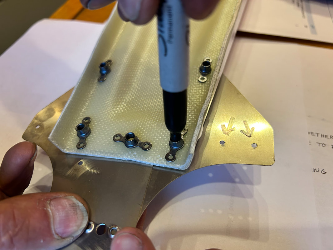
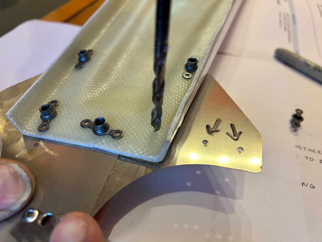
This photo is temporary as you can see many parts are not shown. However, this is the hole that should be drilled next with a #10 through the fibreglass (nose bowl), both stainless doublers, and the fibreglass center cowling.
Remove the nosebowl, center top cowl and loose doubler.
- Install anchor nuts on the three holes you drilled through your top center cowl.
- With the parts on a bench or the floor, screw the two nose bowl halves together with the small loose doubler in position (held with the one screw in the front).
- Attach the top center cowl using the three screws.
- Mark and drill for two more anchor nuts as shown in the images below.
- Drill two #40 holes as marked with two arrows as shown below.
- Countersink holes as necessary.
- Rivet anchor nuts to fibreglass piece only. The two #40 holes can have rivets installed through the nose bowl half.
|
|
STEP 10:Installing the cowling to the nose bowl joining strips.
- Mark the forward outboard side of all your strips at 1" from the front. This line matches the back edge of the nose bowl when installed. - In preparation for your cowling fasteners and crimping, Mark your nose bowl at ~5" spacing starting two inches from the centerline of the top center cowl, ending with the final holes being one inch above the C-channel horizontal nose bowl supports on either side. There should be 6 equally spaced marks on each side for the top joining strips. - Starting with a mark on the center of the C-channels, mark three additional fasteners between the C-channel and the corner of the nose bowl on each side; the bottom mark being one inch from the corner. - Mark five more evenly spaced marks on the bottom flat portion of the nose bowl with one being on the center line in line with the screws for the split front nose bowl. |
|
STEP 11:
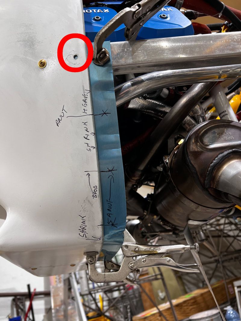
As shown in the below photo, remove the nose bowl edge C-channel screw and slip the bottom joining strips in between the nose bowl and the C-channel as shown. Clamp the bottom with the line barely showing from under the nose bowl. The vertical crease should be in line with the nose bowl edge as well.
In order to do this, you will have to add some crimps in the aft edge of the joining strips to allow for a curve to form. Do not crimp in line with where you have marked your nose bowl for screws as any crimps in line with a fastener will cause issues when installing the nuts later. You can see this in the photo below, crimps have been added in between the marked ANUT (anchor nut) locations.
In order to do this, you will have to add some crimps in the aft edge of the joining strips to allow for a curve to form. Do not crimp in line with where you have marked your nose bowl for screws as any crimps in line with a fastener will cause issues when installing the nuts later. You can see this in the photo below, crimps have been added in between the marked ANUT (anchor nut) locations.
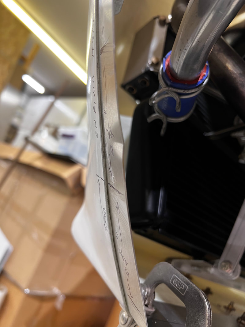
Using a straightedge, hold it against both the fuselage of the aircraft and the nose bowl. Crimp the joining strips until they are parallel with the straight edge as shown in the two comparisons below. The joining strips need to be crimped so that they are parallel with the straight edge all the way up. The new strips require almost no crimping compared to what is shown.
|
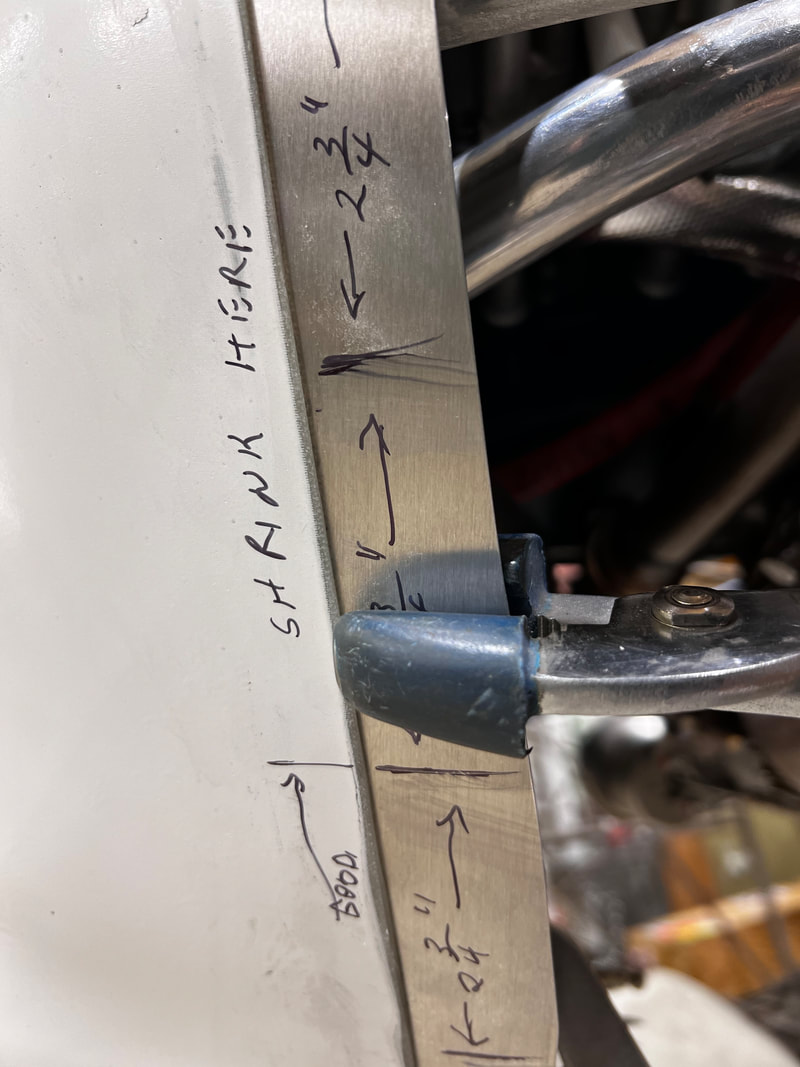
Crimping pliers may vary, but this is how you will adjust your joining strips.
|
|
Needs Crimping:
Aluminum joiner not parallel to straight edge. Crimp bend required.
|
Perfect Alignment:
Crimp bend added and joiner strip is parallel to straight edge. Continue till it is all parallel except for the actual crimps.
|
STEP 12:
Mark out for rivets 1/2" in from the back edge of the nose bowl at one inch increments starting with the first hole just under the C-channels. This may be easier with 1/2" masking tape to use as a guide - its easy to draw on and easy to remove. Use good quality automotive masking tape for best results (home painters tape does not stick well enough in my opinion).
Mark the hole for the screw you removed in step 11. Drill once removed so you do not destroy the anchor nut installed in the C-channel per step13.
Drill and cleco your marked holes with a #40 drill bit. Leave the intersecting hole where the two joining strips meet at the bottom center of the nose bowl.
STEP 13:
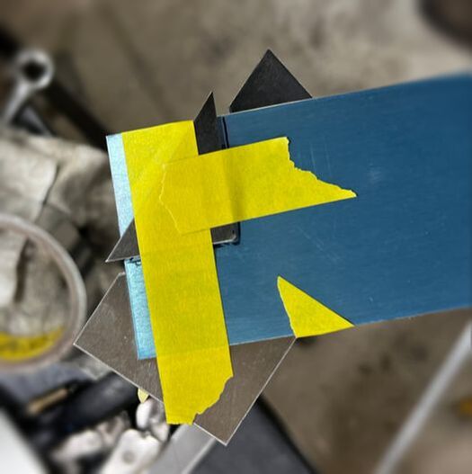
Once your joining strips have been clecoed onto your nose bowl, you will notice that they need to be joggled to fit over the nose bowl halves joining strip. Mark the position of the riveted joining strip on the clecoed joining strip and then draw a line 1/8" bigger around that one as shown.
|
|
Duplicate the inside line on the opposite side of the piece. Place the small triangle of metal (provided in your kit) on that inside line and tape in place. Tape the L-shaped metal piece on the other side lining up with the outside line you drew above. Tape in place.
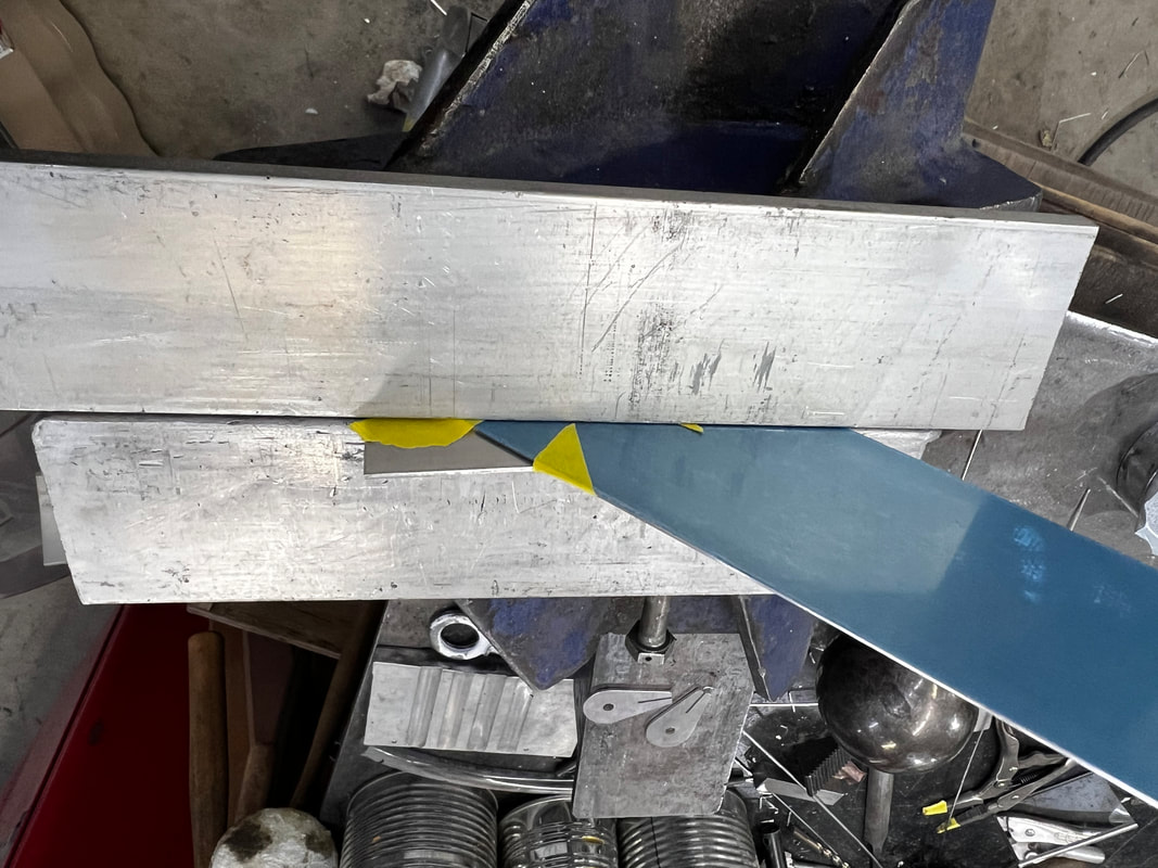
Verify that when this has been clamped together, the bend will go in the right direction.
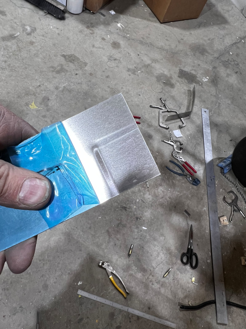
Clamp in a vice with a couple pieces of angle iron or thicker aluminum so that there is a good amount of surface area. Tighten until you can't tighten it anymore (by hand). Release the vice and remove the joggling tools.
Verify that when this has been clamped together, the bend will go in the right direction.
Clamp in a vice with a couple pieces of angle iron or thicker aluminum so that there is a good amount of surface area. Tighten until you can't tighten it anymore (by hand). Release the vice and remove the joggling tools.
|
|
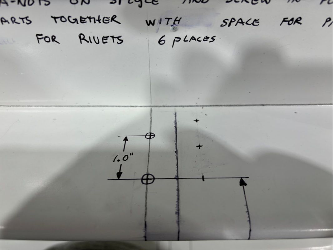
Drill the remaining rivet hole in the left-hand side joining strip (at the bottom center of the nose bowl).
Mark and drill for an anchor nut on the right-hand side joining strip in line with the rest of the screws holding the two nose bowl halves together. The photo below shows this anchor nut installed.
Drill the marked screw hole circled in Step 11 with #10 drill bit.
Mark and drill for an anchor nut on the right-hand side joining strip in line with the rest of the screws holding the two nose bowl halves together. The photo below shows this anchor nut installed.
Drill the marked screw hole circled in Step 11 with #10 drill bit.
Countersink and rivet all rivets in the nosebowl and joining strips
STEP 14:
Once the bottom joining strips are finished, start on the top strips. This is done the exact same way (Follow steps 10-12).
Countersink and rivet all rivets in the nose bowl top joining strips. Start this at the bottom and work your way up and inboard.
Countersink and rivet all rivets in the nose bowl top joining strips. Start this at the bottom and work your way up and inboard.
While following step 10 for the top joining strips, you will need to mark out your spacing for cowling fasteners on your instrument panel to cowling skin (the fasteners should be ~1/2" aft of the edge).
This is because you will need to crimp the instrument panel to cowling skin as shown in the images below to allow for 1" of parallel skin for attaching your ACE cowlings to the Zenith skin. Do not crimp farther aft than where your cowling skin will cover.
This is because you will need to crimp the instrument panel to cowling skin as shown in the images below to allow for 1" of parallel skin for attaching your ACE cowlings to the Zenith skin. Do not crimp farther aft than where your cowling skin will cover.
|
|
This photo shows the end of step 12 on the top right joining strip.
NOTE: Your upper joining strips will not go all the way to the top. On the Lh side trim so you do not have a sharp edge when reaching for your radiator water cap. On the Rh side cut off at an angle so you do not impale yourself on the sharp end at any time in the future. Do this after your side cowl attachment fasteners are installed so you do not cut off too much.
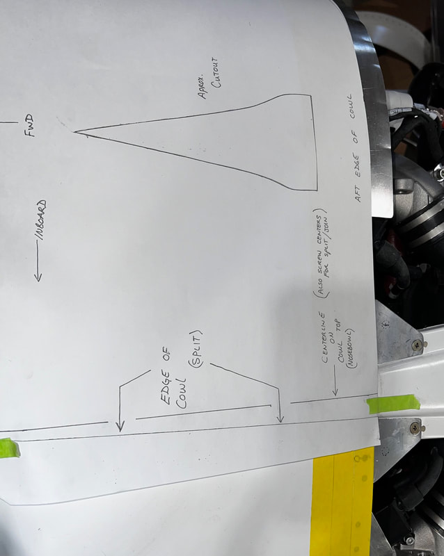
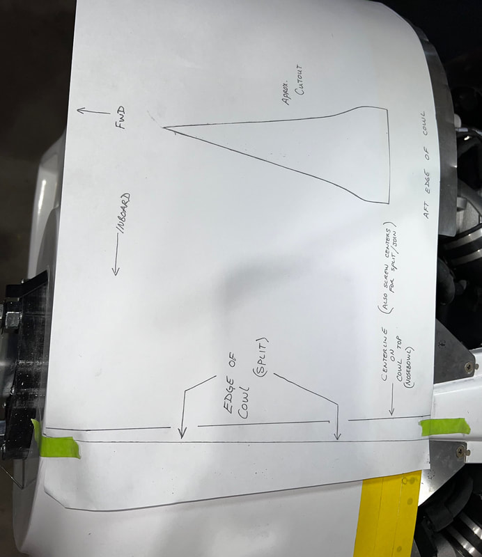
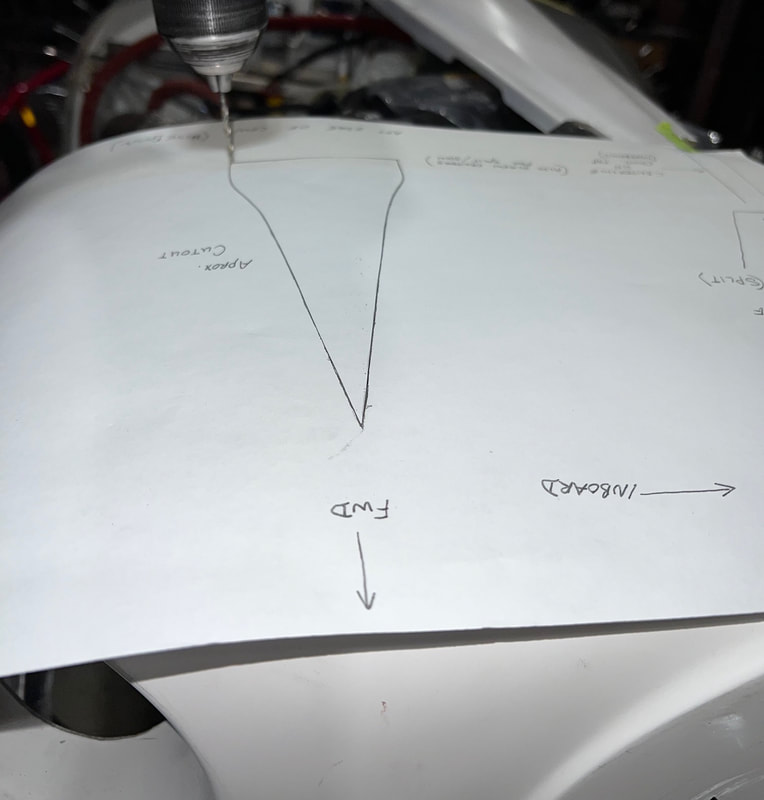
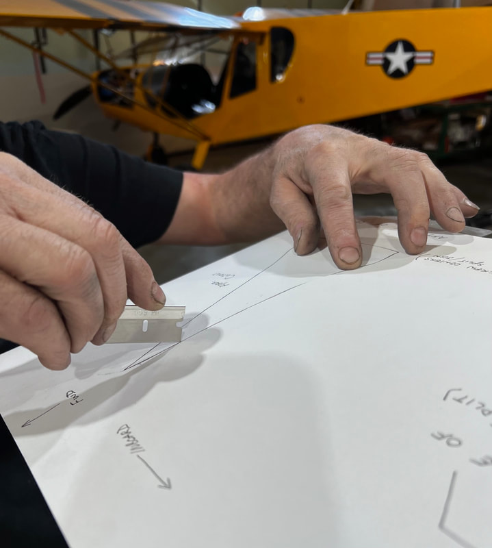
STEP 15: Installation of Naca Scoop
Place self explanatory paper template on Rh side of the nose bowl as shown. Drill corners with #40. Cut out template and mark cut line on nose bowl. Cut out nose bowl and install duct.
The scoop and deflector go on the underside of the nose bowl. This can be fibreglassed in and or riveted in.
This is finished when fibreglassed in.