ACE Package - Firewall Kit (Part 1 of 4)
SKU:
SF 00K
$982.00
$982.00
per item
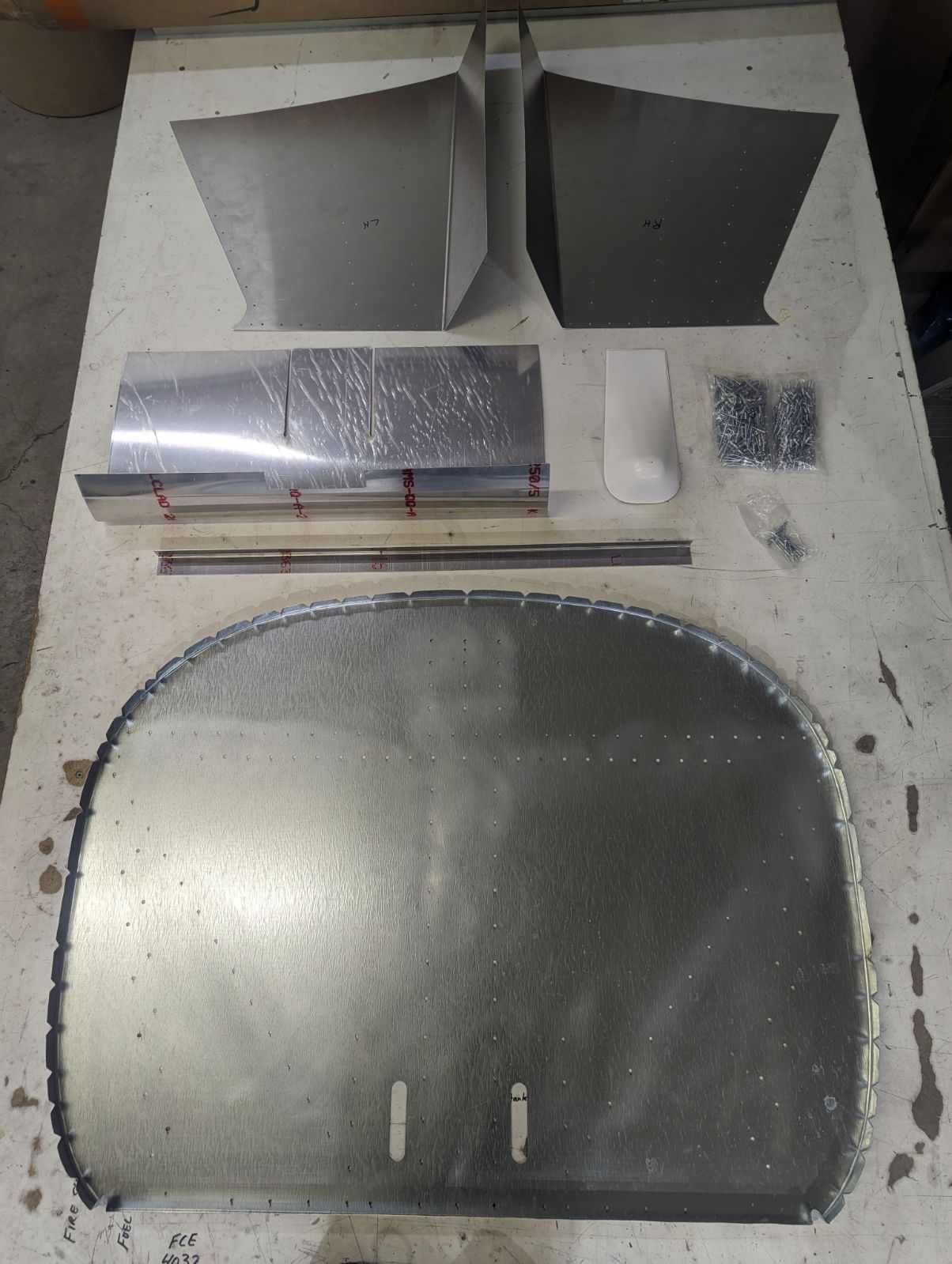
This slightly larger firewall takes the bent look out of the Zenair products with a Rotax 912is, 914, 915is, and 916is engine in them. It comes with new side skins and a belly panel with fibreglass ends. The belly panel is to make the engine cool better.
It can be used on any Rotax ring mount engine, but you'll need all four kit parts.
It can be used on any Rotax ring mount engine, but you'll need all four kit parts.
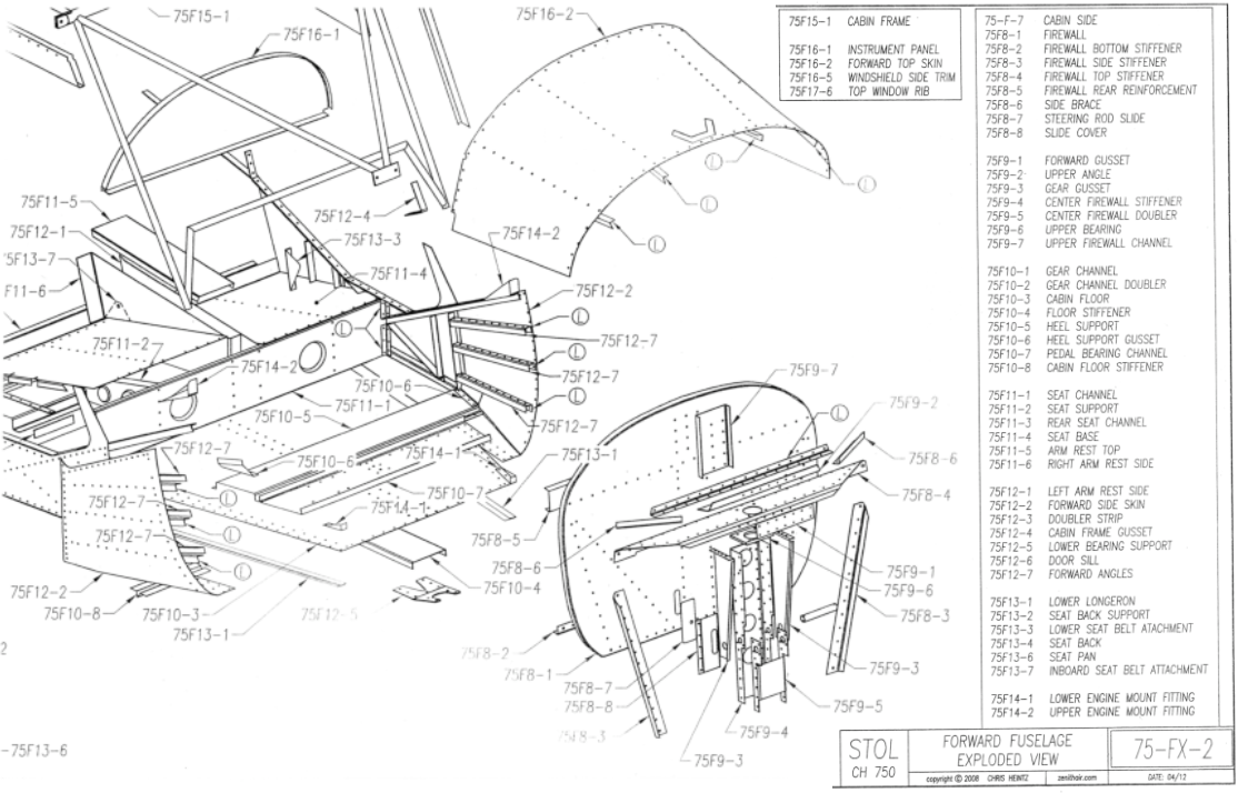
Part Identification Reference Documents (From Zenith):
ACE Package Installation Instructions Kit (1 and 2 of 4):
Previously Assembled Aircraft Only:
For prebuilt aircraft, remove old firewall (75F8-1) and everything attached to it: Firewall Bottom Stiffener (75F8-2), braces, stiffeners, forward side skins (75F12-2), forward angles (75F12-7), lower engine mount fittings (75F14-1), etc.
You will be reusing all these parts upon re-assembly, so be careful not to damage them.
You will be reusing all these parts upon re-assembly, so be careful not to damage them.
New Builds Only:
Fit and cleco ZENITH Firewall (75F8-1) and forward side skins (75F12-2), engine mount fittings (75F14-1/2) as per Zenith's instructions.
Remove Firewall (75F8-1), Firewall Bottom Stiffener (75F8-2), forward side skins.
Remove Firewall (75F8-1), Firewall Bottom Stiffener (75F8-2), forward side skins.
Step 1: For Everyone
Cleco the Firewall Bottom Stiffener (75F8-2 just removed) to your ACE Firewall. Back-drill bottom vertical holes in the stiffener through the ACE firewall bottom flange.
Remove Firewall Bottom Stiffener (75F8-2) and replace with the new longer stiffener supplied with your kit. Put the Zenith bottom stiffener away as it will not be required for the remainder of your installation. Clamp the new longer stiffener firmly in place against the firewall bottom flange and forward face.
Using the firewall as a guide, back-drill all holes into the new longer stiffener.
Add two extra new holes on each end about 10mm from the end of the stiffener. One going fore and aft through the firewall and new bottom stiffener and 2nd going vertically through the stiffener, firewall and eventually the forward side skin.
Remove the new longer stiffener.
De-burr all holes in firewall and the ACE stiffener. Cleco back together.
Install ACE firewall and stiffener onto aircraft and cleco in place to the Cabin Floor (75F10-3). This positions the ACE firewall in the same position as your original firewall (Zenith's spec).
Cleco Lower Engine Mount Fittings (75F14-1) to the Lower Longeron (75F13-1).
Clamp the Upper engine mount fittings (75F14-2) and Cabin Frame (F75F15-1) to the ACE firewall.
Be sure that the lower portion of the firewall is level with the bottom of the aircraft and that the Lower Longerons (75F13-1) are straight (not bowed up or down). A support of some kind is helpful here. You may have to re-clamp the upper engine mount fittings (75F14-2) and the Cabin Frame (F75F15-1) to align. The Cabin Frame should be centered on the top of the firewall.
Step 2:
Cleco new forward side skins to the upper longerons and the forward vertical row of holes on the cabin side below the forward door post.
Starting at the top and working down, pickup holes from firewall into new side skins between where the Forward Angles (75F12-7) go. Using the same size and number of rivets as per Zenith forward side skins (75F12-2). As you drill these holes, verify the edge spacing between the new forward side skins and the ACE firewall. Cleco immediately after drilling each hole. Once you get near the bottom, the side skin will not fit tightly against the firewall due to binding against the lower longeron. Once you get to this point, stop and remove the new side skin. Slip the bottom of the side skin between the Lower Longeron (75F13-1) and the Cabin Side (75-F-7).
Continue marking and drilling the holes in the new side skins and firewall to the bottom, pushing it in as you go. You may need someone to help push the side skin in/up with a piece of wood (2x4) while you drill the remaining holes through the lower longeron and the cabin floor.
Drill the holes in the aft vertical row of the new side skin to the final hole size in the cabin side A4 or A5 rivets depending on the hole size of the cabin side structure (Keep them the factory sizes).
Fit, drill, and cleco the Forward Angles (75F12-7) as per Zenith instructions. Be sure that all holes are upsized to the final size. Remove the side skin and cleco the original Zenith side skin to it as a guide, then back-drill any holes not able to be drilled due to the heal support (75F10-5), etc.
Trim inboard bottom edge of the new forward side skin to give a 10mm edge distance to the inboard most row of holes you drilled through the cabin floor skin.
De-burr all holes in the new side skin and the firewall and cleco everything from the upper longeron down. Bolt on lower engine mount fittings in position (through floor skin, side skin, and lower longerons).
Step 3: Includes Instructions For ACE Engine Mount (2 of 4)
Cleco all Zenith supplied firewall stiffeners, supports and doublers to both sides of the firewall (as shown in the parts diagram above).
This is an excellent opportunity to install our Steering Rod Swivels! Check them out here!
Drill four 3/8" engine mount bolt holes through the firewall and any supporting structure.
Deburr holes and install your ACE engine mount (part 2 of 4) using the truss to firewall install kit.
Clamp your center upper engine mount brace to firewall and 75F15-1 cabin frame.
Two 1/4" holes can now be installed one on each side. Before drilling verify firewall is straight. Reclamp if necessary and drill. Disassemble everything and deburr.
Now is an excellent time to lay out, fit and drill for the fuel filter & mounting, Fuel gascolator, solenoid, ECU mount, water overflow bottle, oil tank mounting, fuel shut off, and fuel pump mounting kits as the firewall can be removed from aircraft and laid flat on a table to fit the above items.
Before drilling you may want to cleco items just removed (in prebuilt before step 1 or fit new new builds pieces) in position and verify fit in case one of us used a wrong measurement and there is interference.
Drill and cut out holes as required to install other kits. Deburr all holes. Rivet all items in place except for the rivets holding the ECU mounting bracket in place (these will go in after the master and starter solenoid kit is installed and after all the top skin holes are picked up). Do not rivet bottom row of holes running fore and aft in lower bottom firewall stiffener as these will be used by the bottom swooped chin skin supplied in your kit. Cleco this assembly to the aircraft along with forward side cheek skins fit in step 2. These can now be riveted in except for upper longerons as the top skin needs to be fit to that over lapping row.
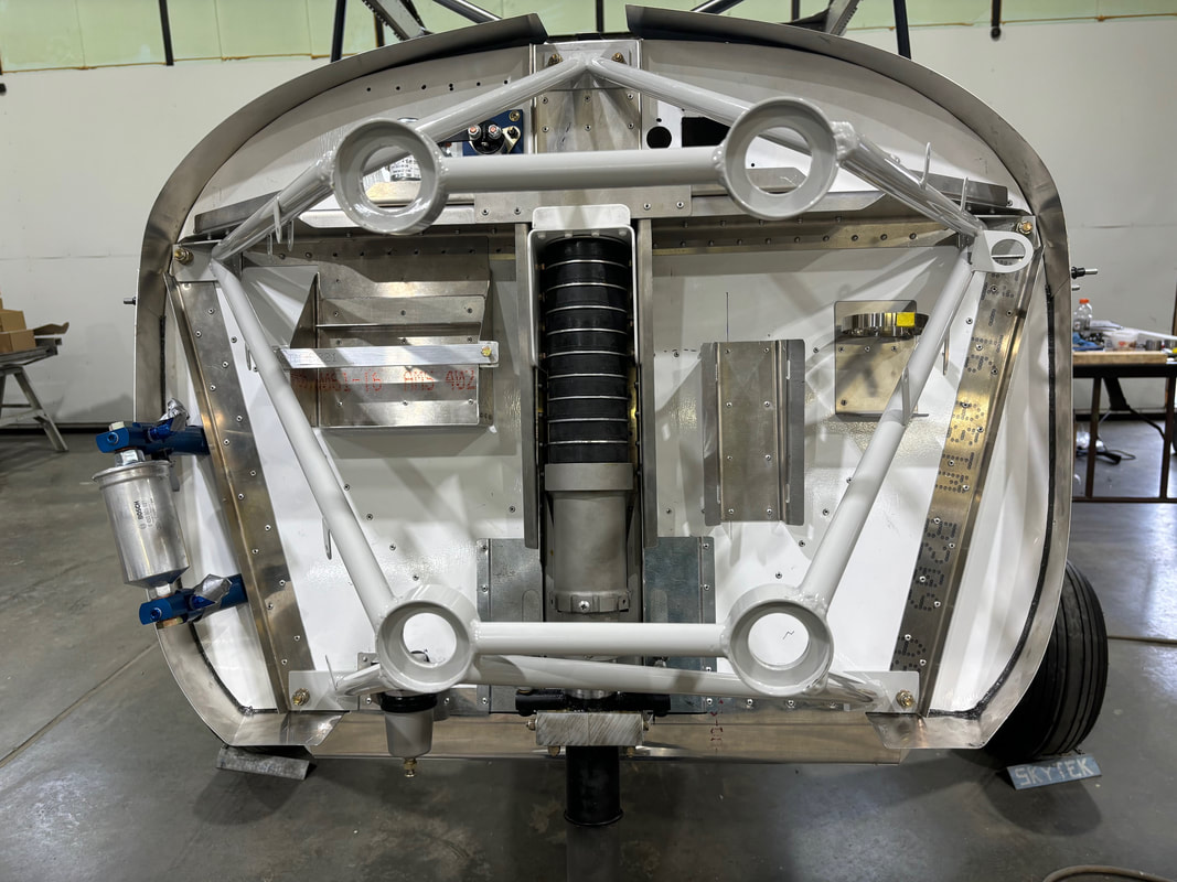
Be sure all vertical rivets and bolts are installed in belly skin side skins and firewall. The only ones that do not need to go in are the aft two bolts for the center rudder pedal cross bar bearing and the rivets running side to side where the aft edge of chin swoop will be riveted.
STEP 4:
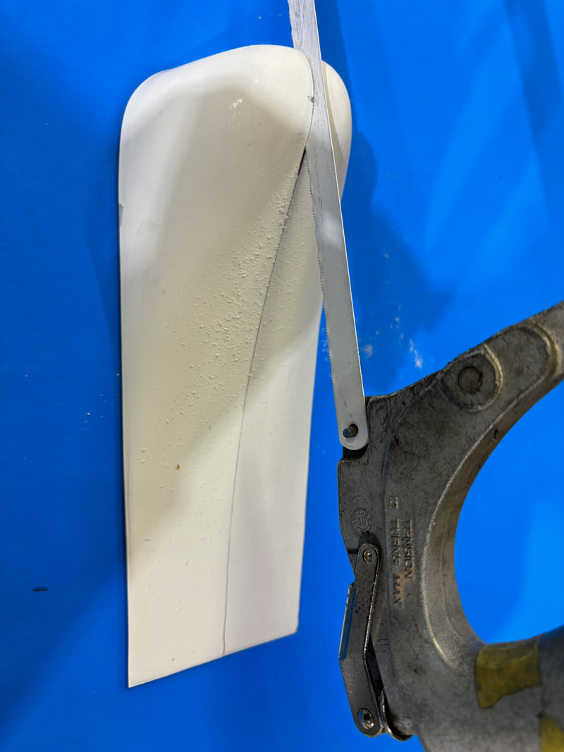
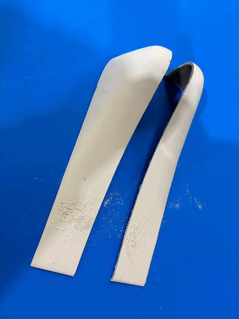
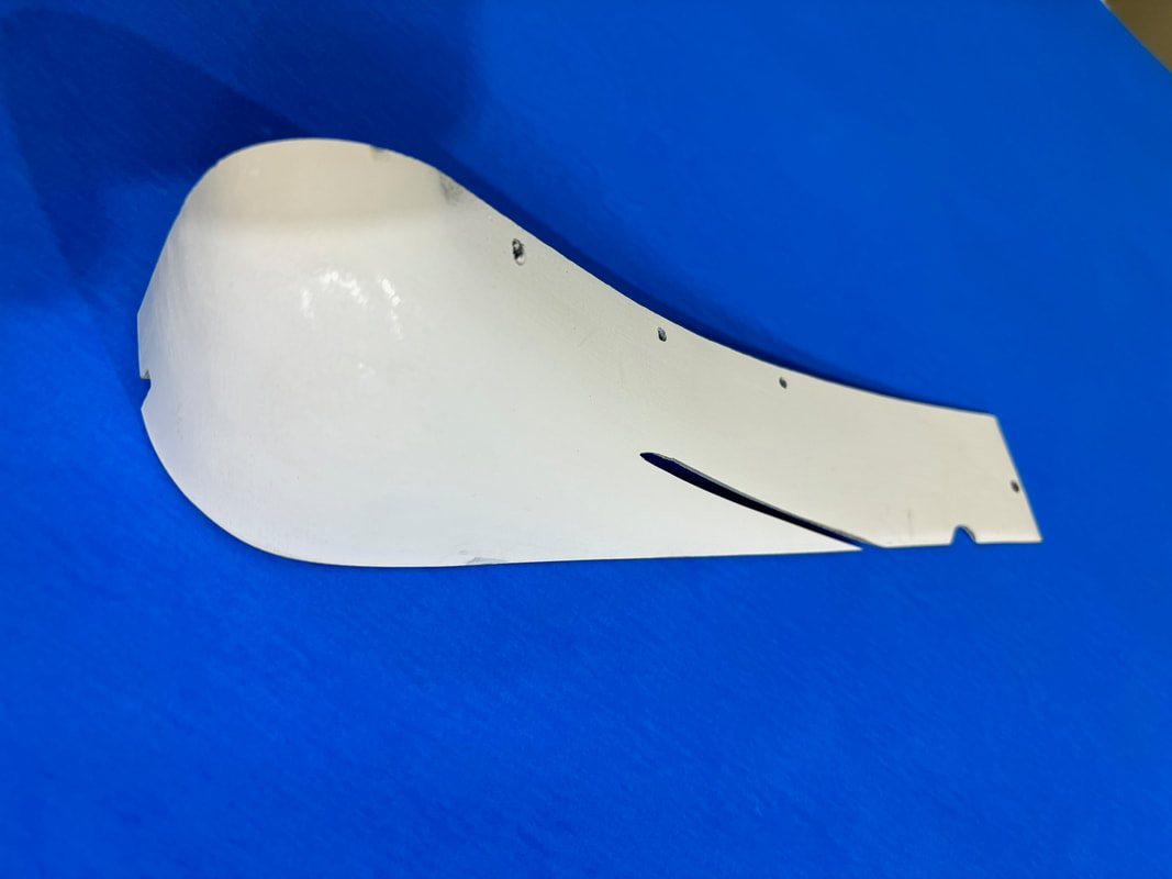
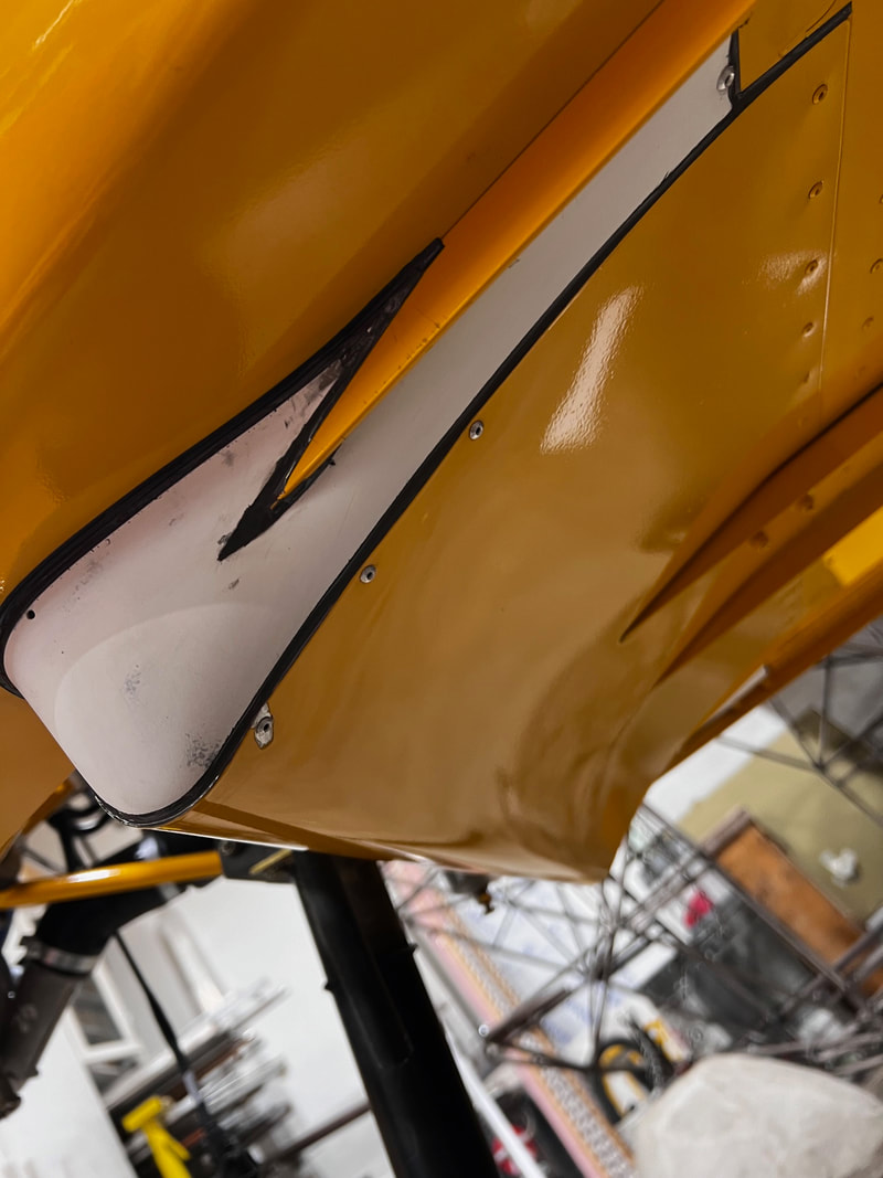
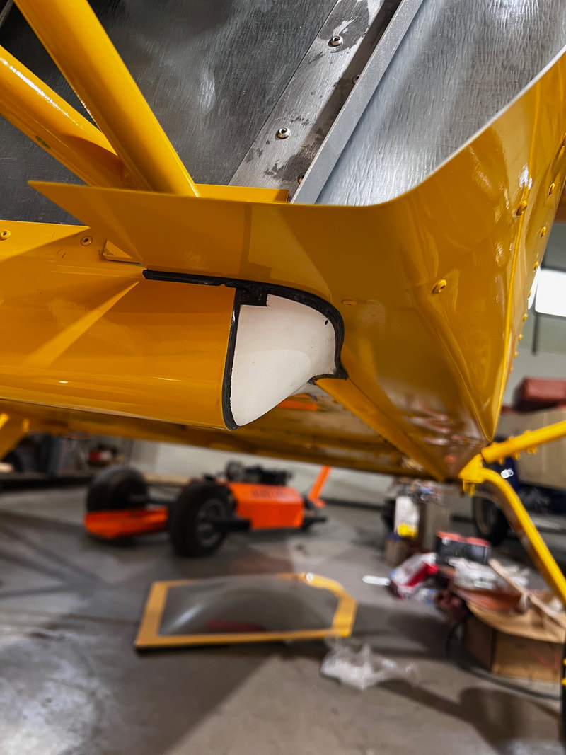
In preparation to fit the swoop cut the fiberglass swoop end cap in two down the center. This gives you two parts. One for each side.
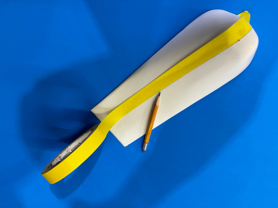
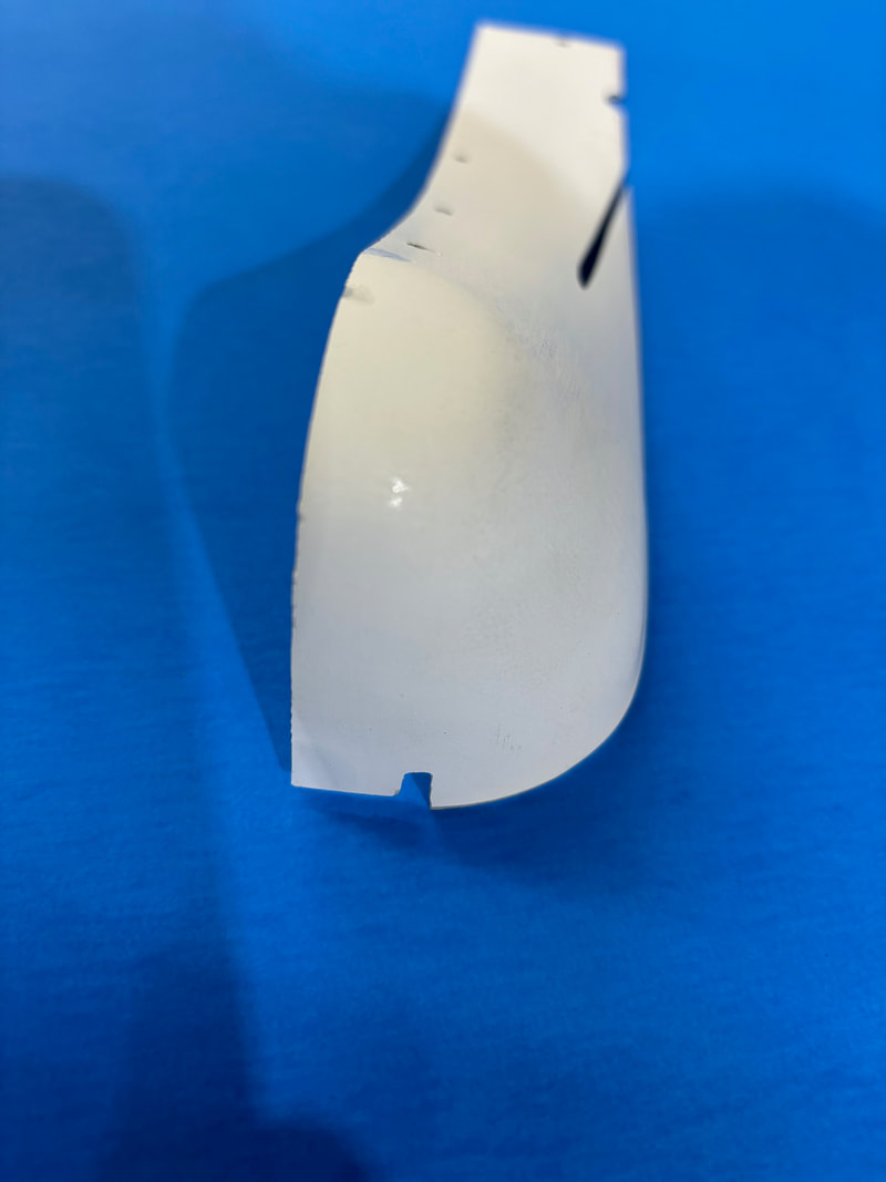
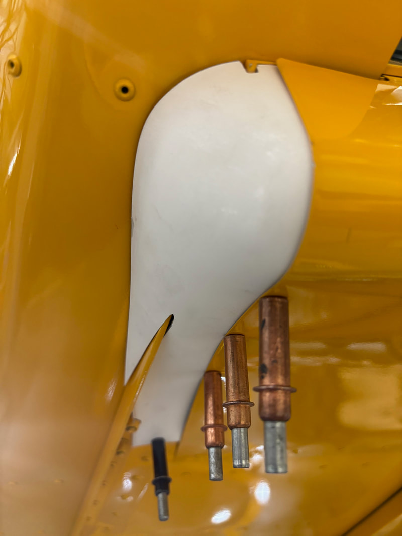
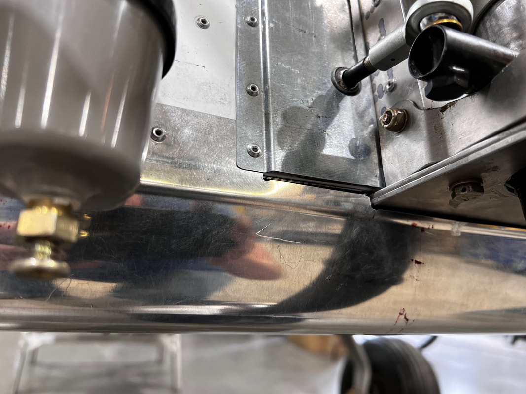
Slide the swoop up into position centered on the firewall. You will have to trim the outboard edges to clear the side cheek skins. You may have to trim the center area more as well. Bring the whole skin up until it fits the fibreglass swoop end caps you just cut. Fit the end caps by cutting them to fit the lower longerons. Take your time. A 1/2" overlap is good, so 3 or 4 A4 rivets can be installed to hold the end caps to chin swoop.
Rh side shown. Lh is the same only opposite.
Rh side shown. Lh is the same only opposite.
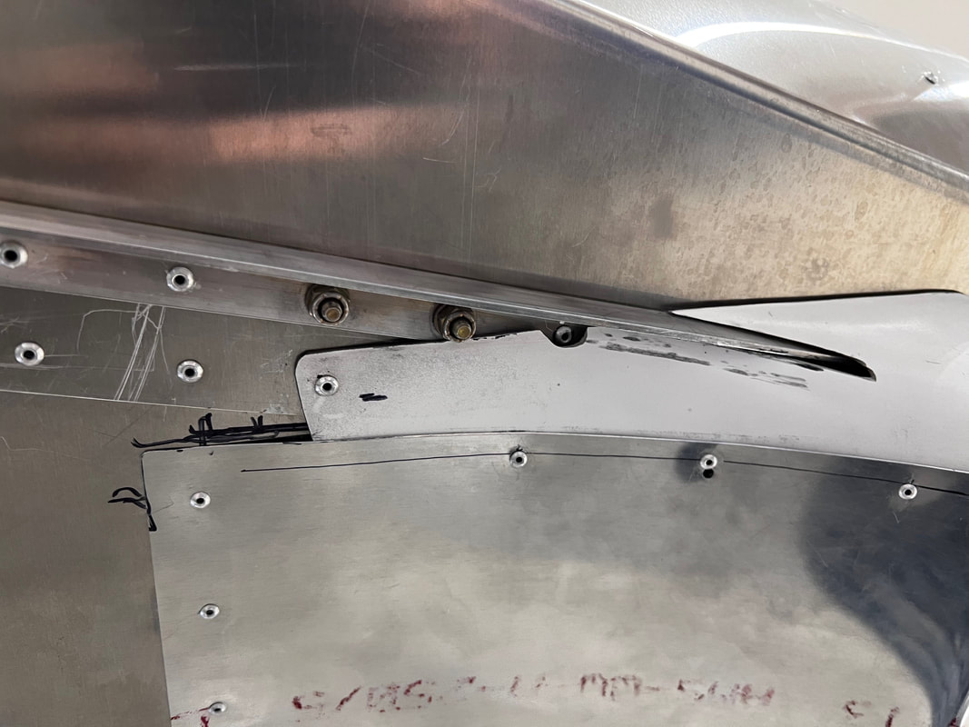
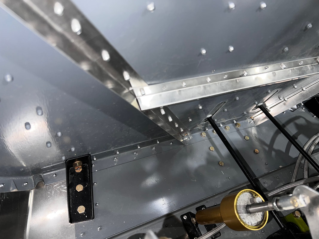
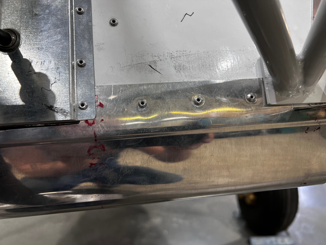
Pick up aft row of holes using existing rivet locations. Pick up aft two holes in rudder pedal center bearing block and drill larger hole for forward bolt as seen above.
Be sure that the front is trimmed to allow the steering rod seal to move freely up and down. Deburr and rivet in position as shown above and below.
Be sure that the front is trimmed to allow the steering rod seal to move freely up and down. Deburr and rivet in position as shown above and below.
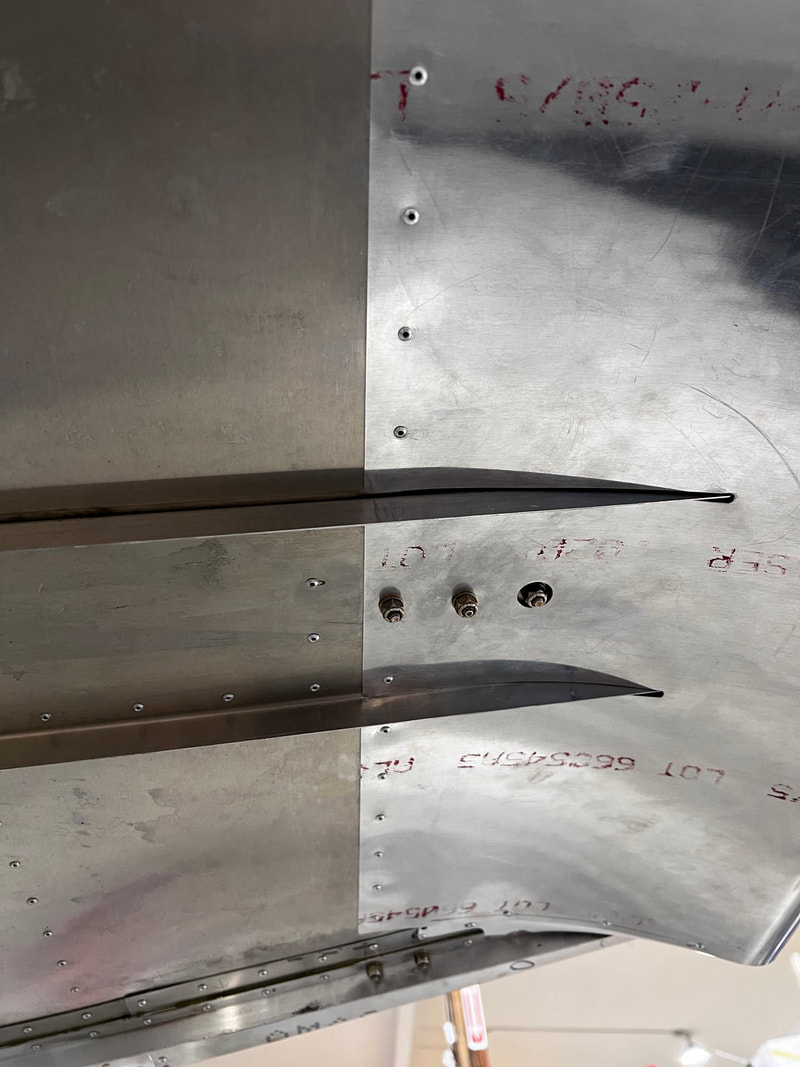
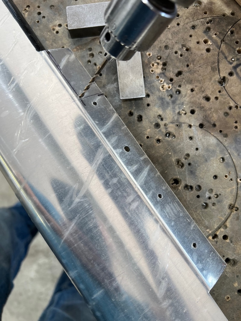
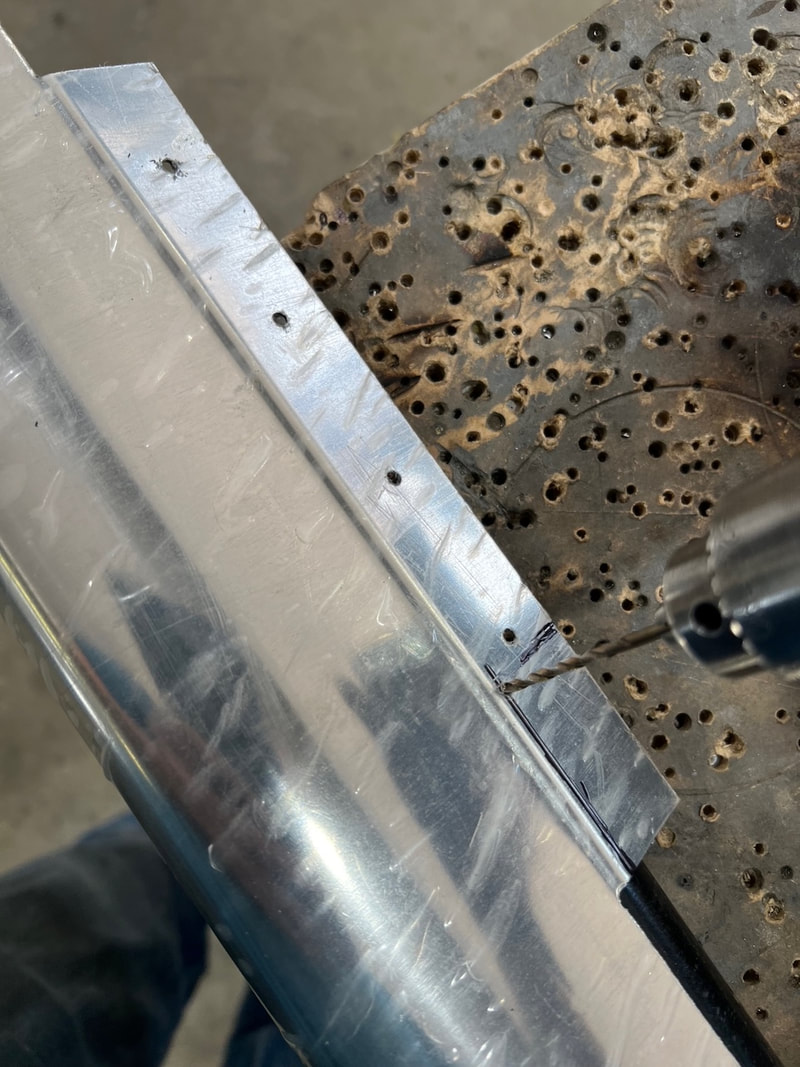
This shows how I make a corner. Drill corner then cut to hole leaving a radius.
|
|
After riveting and prior to paint it is a good idea to seal the edges up with something like Pro-seal available at Aircraft Spruce. Use the PR-1422B-2, CS3204 B-2 or equivalent. A small #10 drain hole at each lower end is a good idea in case it gets water in it.
You are now finished this installation.